GEOMETRIES
1st
AIAA CFD High Lift Prediction Workshop
IGES Geometry Files:
The
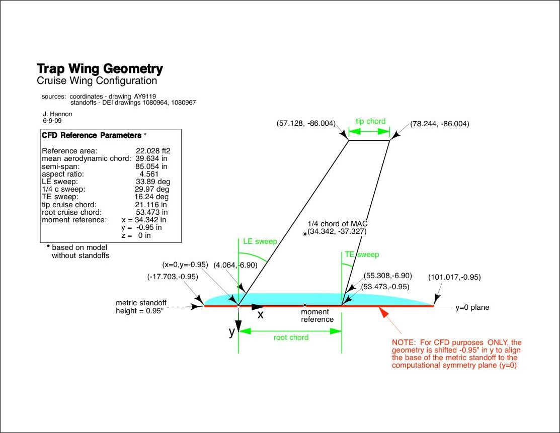
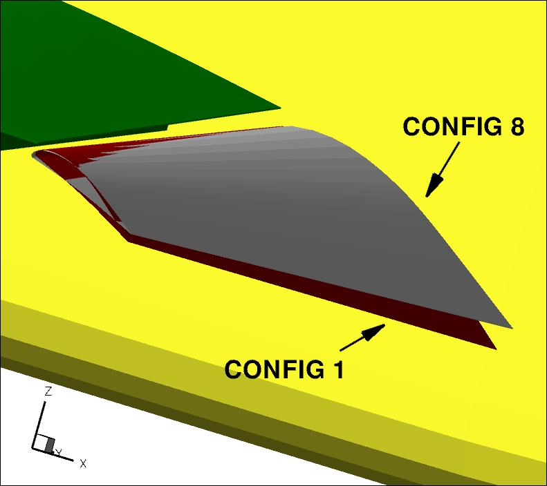
following IGES geometry files are based on measured deployed coordinates, and also include a relevant
y-direction shift as detailed in the figure below. All grids are to be constructed using these
particular files.
Note that
there were several minor differences in the defined flap position during the course of the
testing campaign (discussed in more detail in AIAA Paper 2011-862). The position used here was from 2002 Quality
Assurance (QA) data.
This position differs slightly from the original 1998/1999 geometry definition.
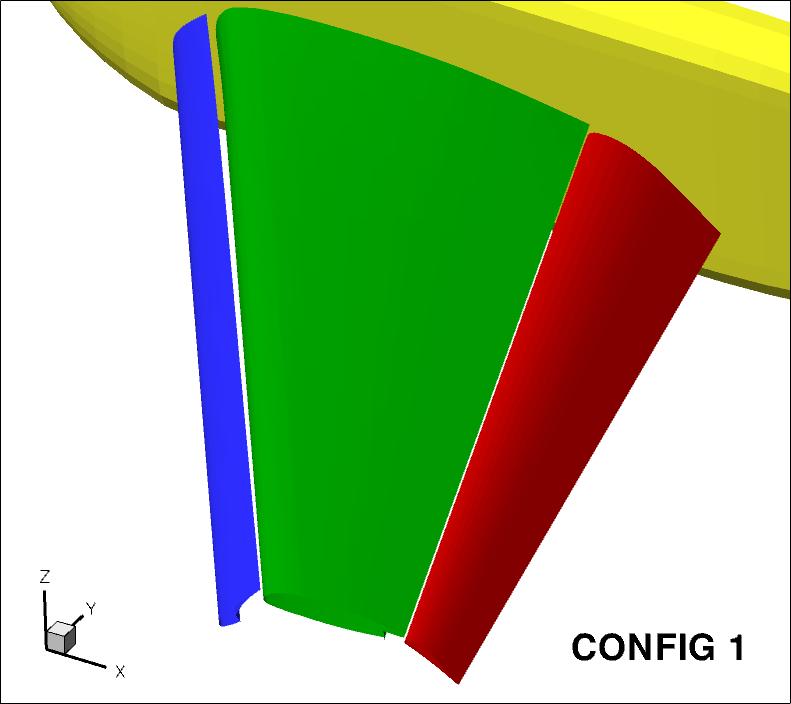
- Configuration 1 - Slat 30, Flap 25 full span:
***Updated 10-22-09***
- Note that a very small "leakage" or "gap" of order 10e-3 units
was discovered in the IGES
file in the slat cove near the wingtip, inside the cove kink.
Most people have not encountered grid generation
problems because of this, so corrective action has not been
taken. Nonetheless, the user should be aware in
case problems are experienced.
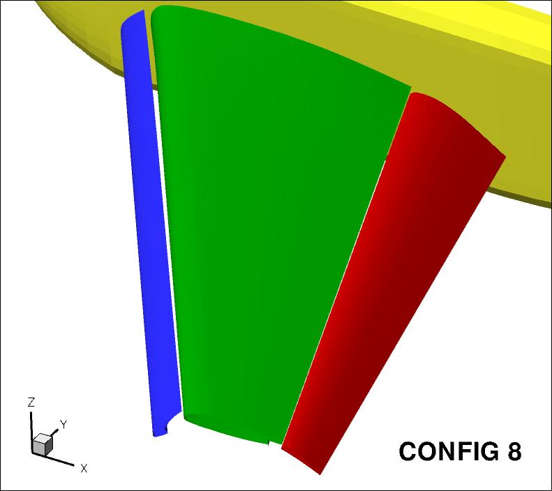
- Configuration 8 - Slat 30, Flap 20 full span:
(The above IGES geometry files have been read successfully in the following third-party
CAD packages and grid generation tools: CATIA V5, VGRID/Gridtool V4.0, ICEMCFD V11.0, Star-CCM+ V4.02,
and Gridgen V15.13.)
ProE Geometry Files:
The geometry files are
also available as ProE files (Configuration 1 only).
Note, however, that the brackets are surfaces, not solid models.
- Configuration 1 - Slat 30, Flap 25 full span:
Note: HiLiftPW participants
are required to run on one of the
provided grids
if possible. Participants are also
welcome to create their own grids, but they must be uploaded to the HiLiftPW Committee.
Geometric Reference Parameters:
Download pdf version of the above cruise configuration diagram:
cruisediagram-09June09.pdf
Data file with approximate local chord (max length line) for each element, based on model without standoffs:
TrapWing_chords.dat
Return to: High Lift Prediction Workshop Home Page
Page Curator and NASA Official Responsible for Content
Christopher Rumsey
Last Updated
September 6, 2011
Privacy Act Statement
Accessibility Statement
