
Summary of Model Geometry
| Model semi-span, b/2 (in) |
|
| MAC (in) |
|
| Model reference area Sref/2,(ft2) |
|
| Aspect Ratio AR |
|
| Leading Edge Sweep, Lle(deg) |
|
| Quarter -Chord Sweep, Lc/4(deg) |
|
| Taper Ratio |
|
| Flap Chord Ratio |
|
| Wing Root t/c (side of body) |
|
| Wing Tip t/c |
|
| Slat Chord (normal to l.e., in) |
|
| Body pod length (in) |
|
| Body Pod Width (in) |
|
| Body Pod Height (in) |
|
| Slat Bracket Location (2y/b) |
0.64, 0.77, 0.94 |
| Flap Bracket Location (2y/b) |
0.61, 0.80 |
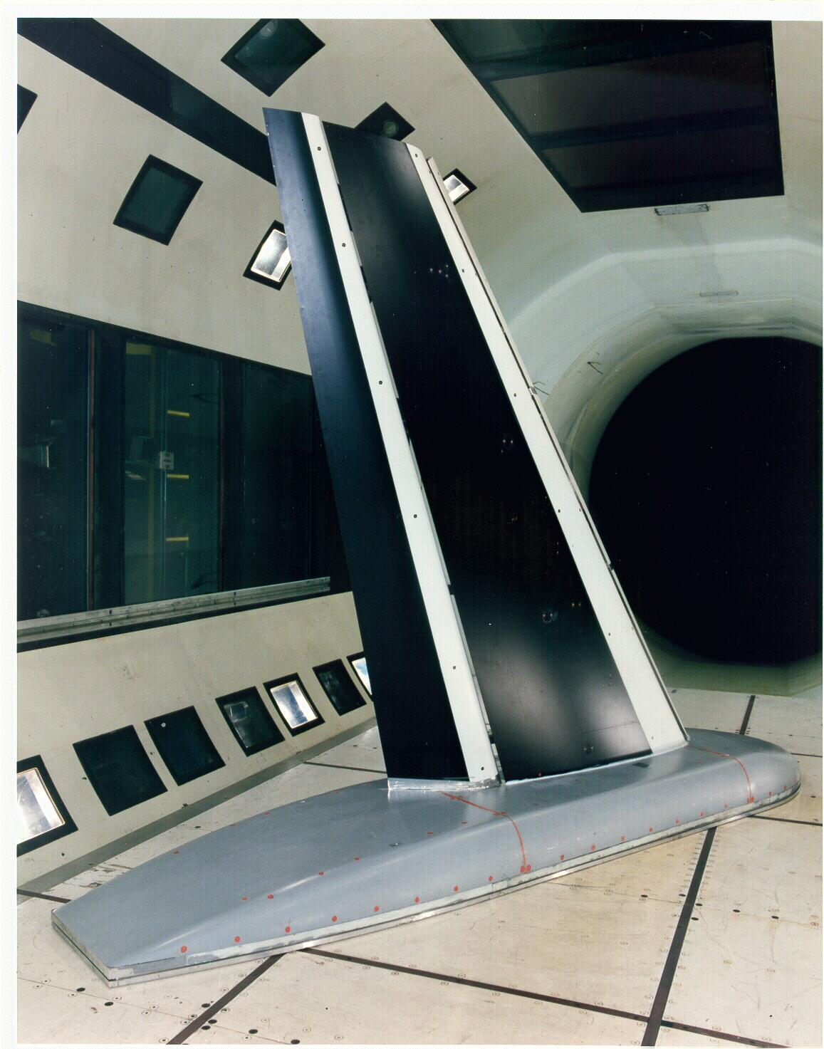
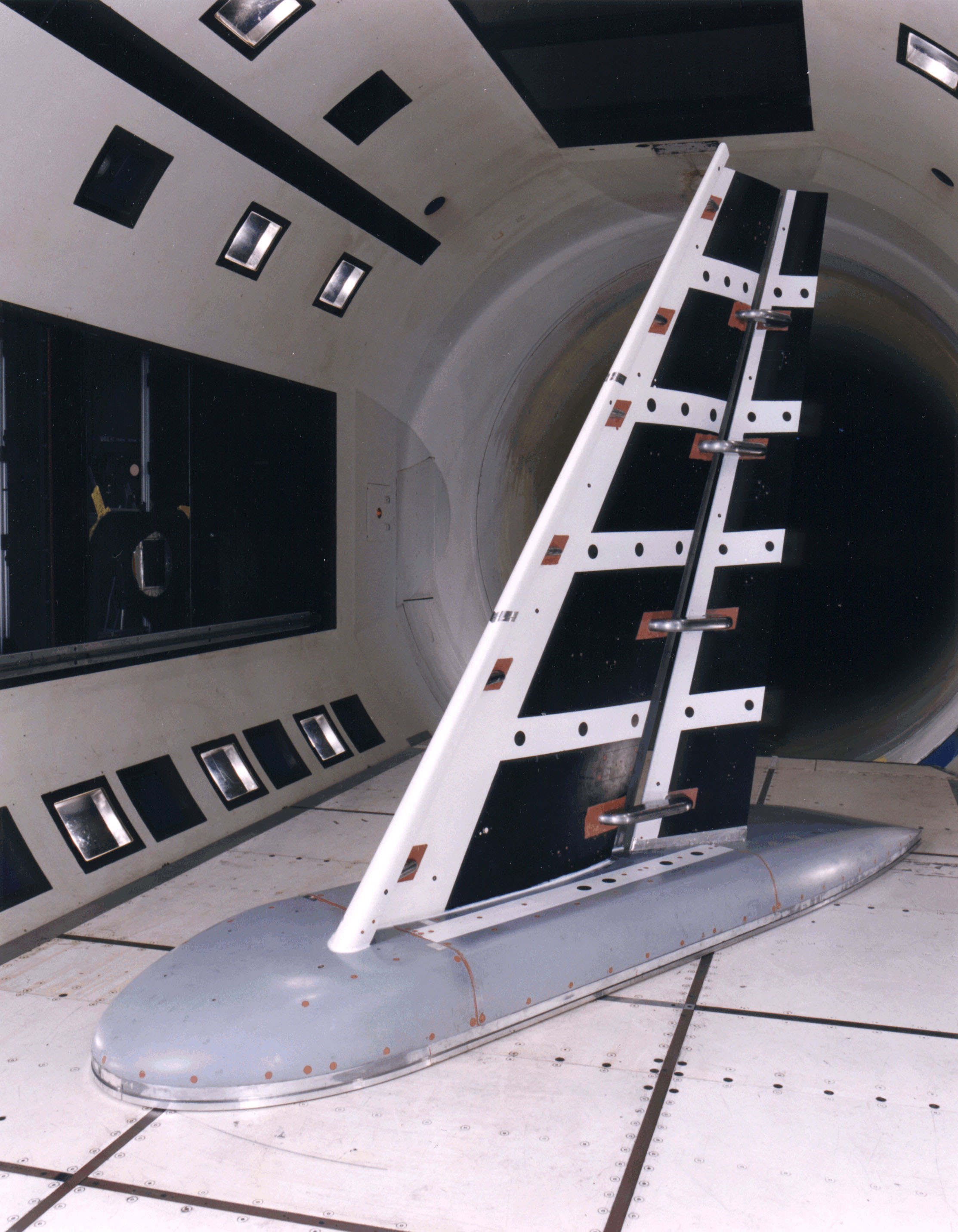
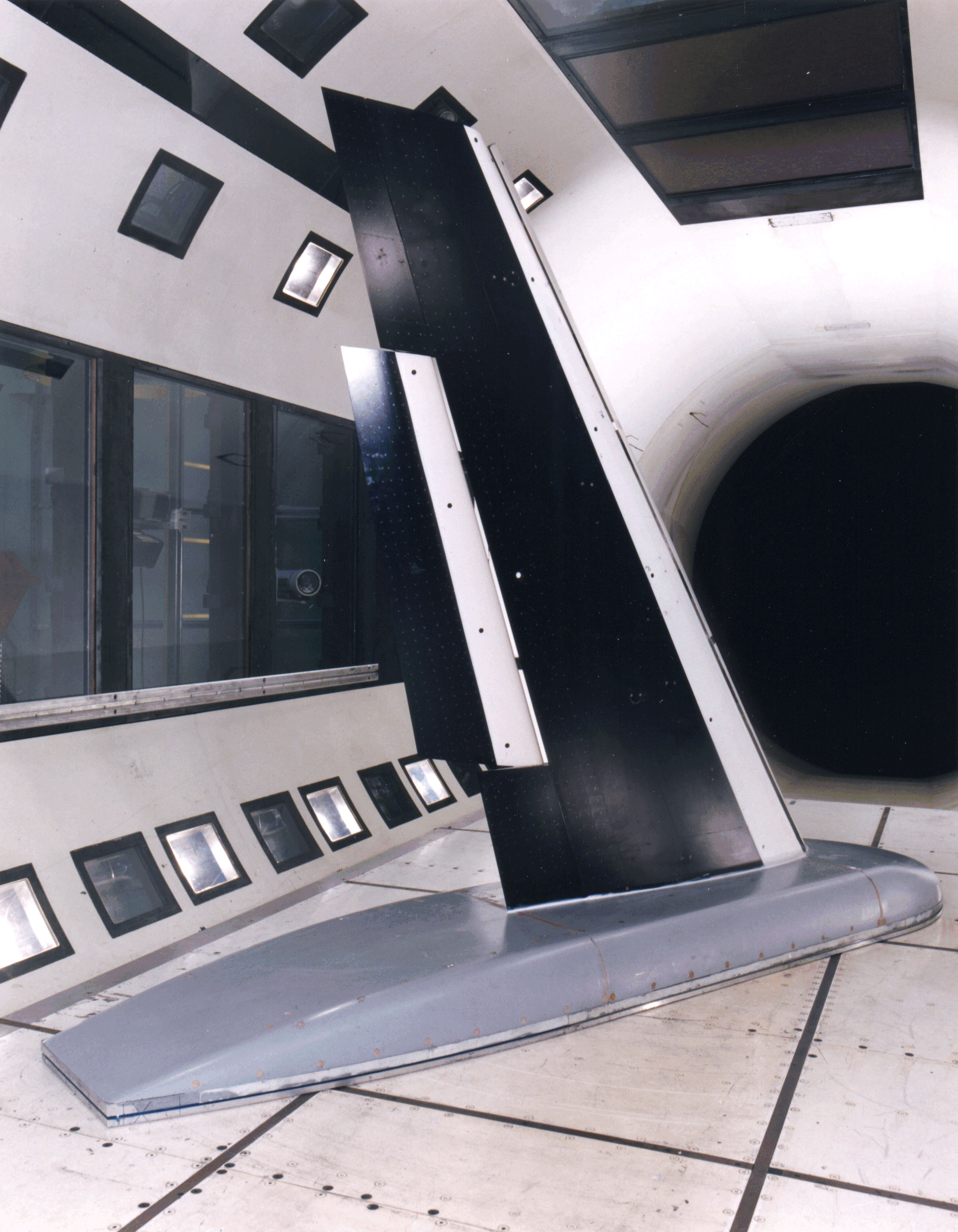
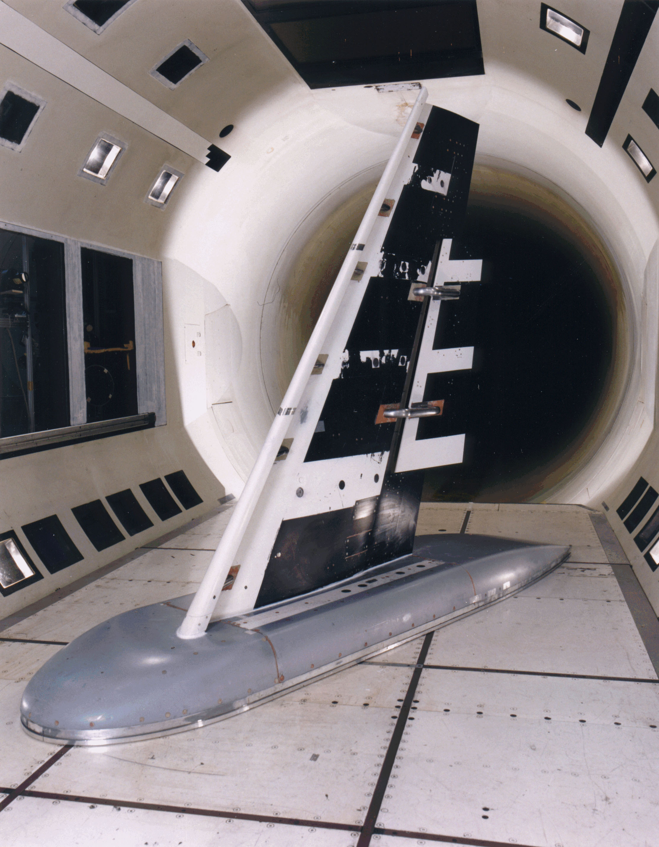
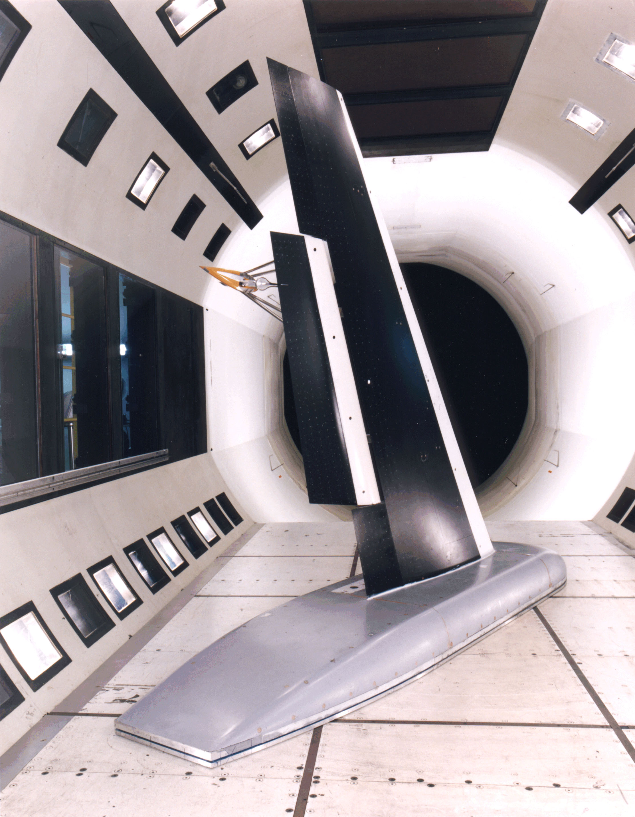
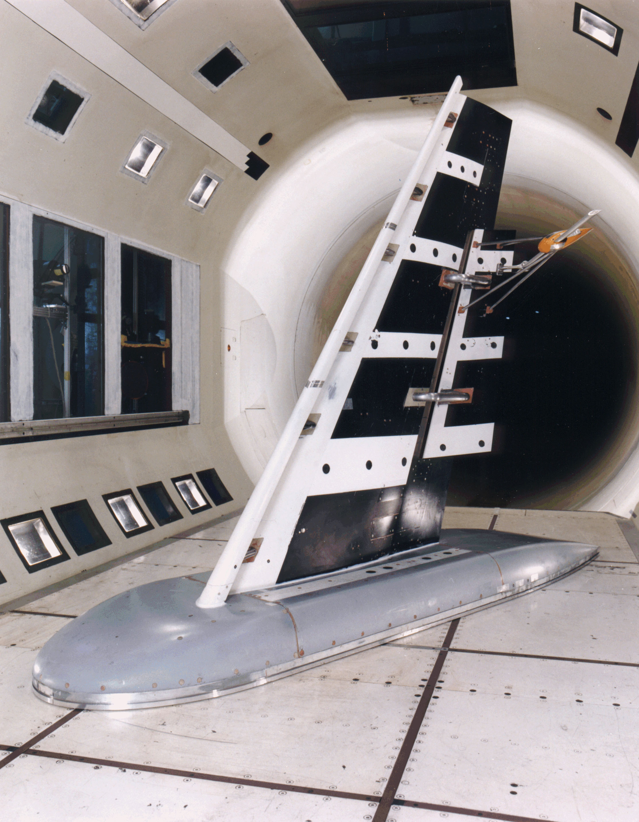
The model, originally designed and tested in the late 1980’s as a simpleswept wing, was highly modified for the NASA AST/IWD program. The wingspar and body pod were retained from the original model, the slat was retainedfrom more recent testing of the same model, and all other components ofthe main element and flap were new.
The leading edge is constant chord, full-span slat, sealing to the side-of-bodyat
all deflections. Six brackets attached the slat to the wing. The trailingflap
is single-slotted, with constant flap chord ratio (cf/c=0.3)across
the span. The flap was tested as both a full-span and part-spanconfiguration.
For the full-span testing, the flap was sealed to the side-of-body.The
part-span flap covers 0.26 < h < 0.75.Sectional
cuts through the positioned geometry for the full-span flapslanding configuration
are shown below.
Cuts through baseline full-span landing flaps configuration at h =0.17,0.50,
and 0.85.
return to Data Archive home page
Page Curator and NASA Official Responsible for Content
Judith A. Hannon
Last Updated
August 5, 2011