MINI-TUFT IMAGES
1st
AIAA CFD High Lift Prediction Workshop
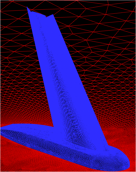
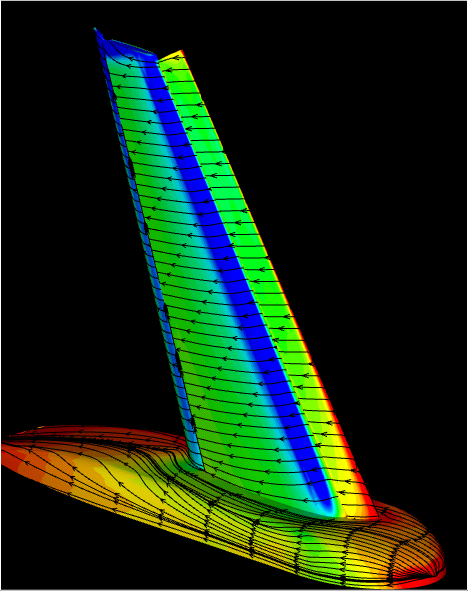
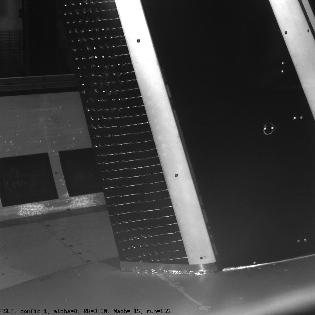
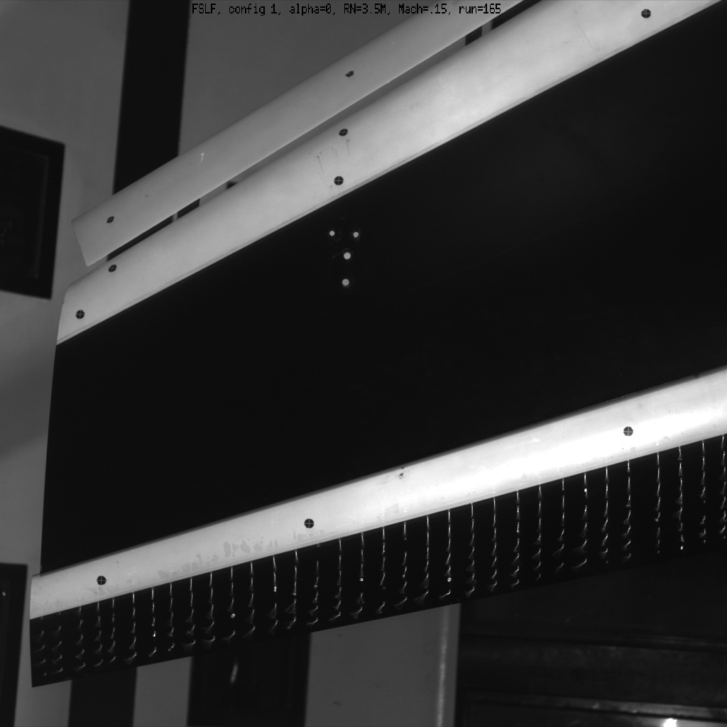
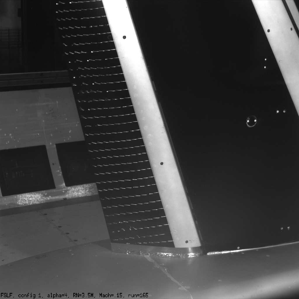
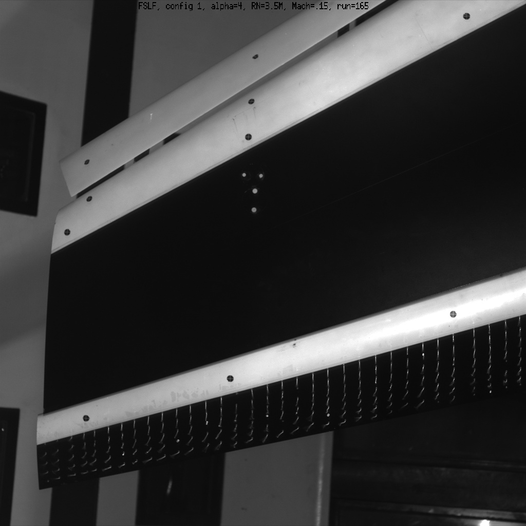
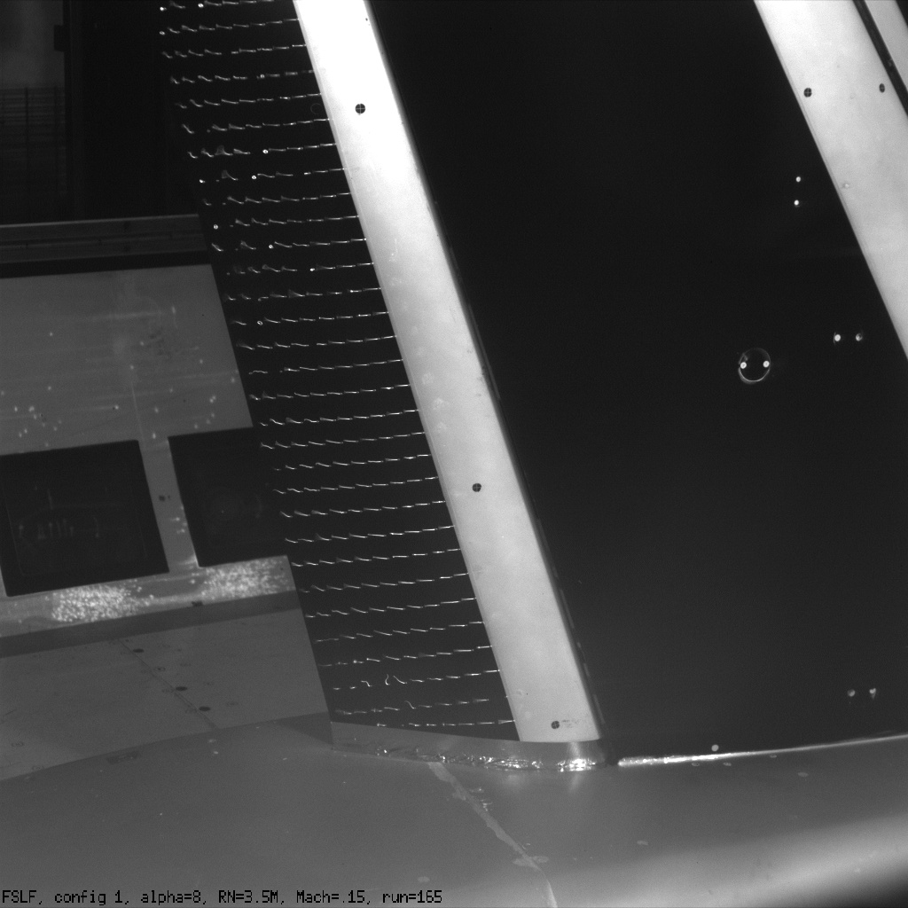
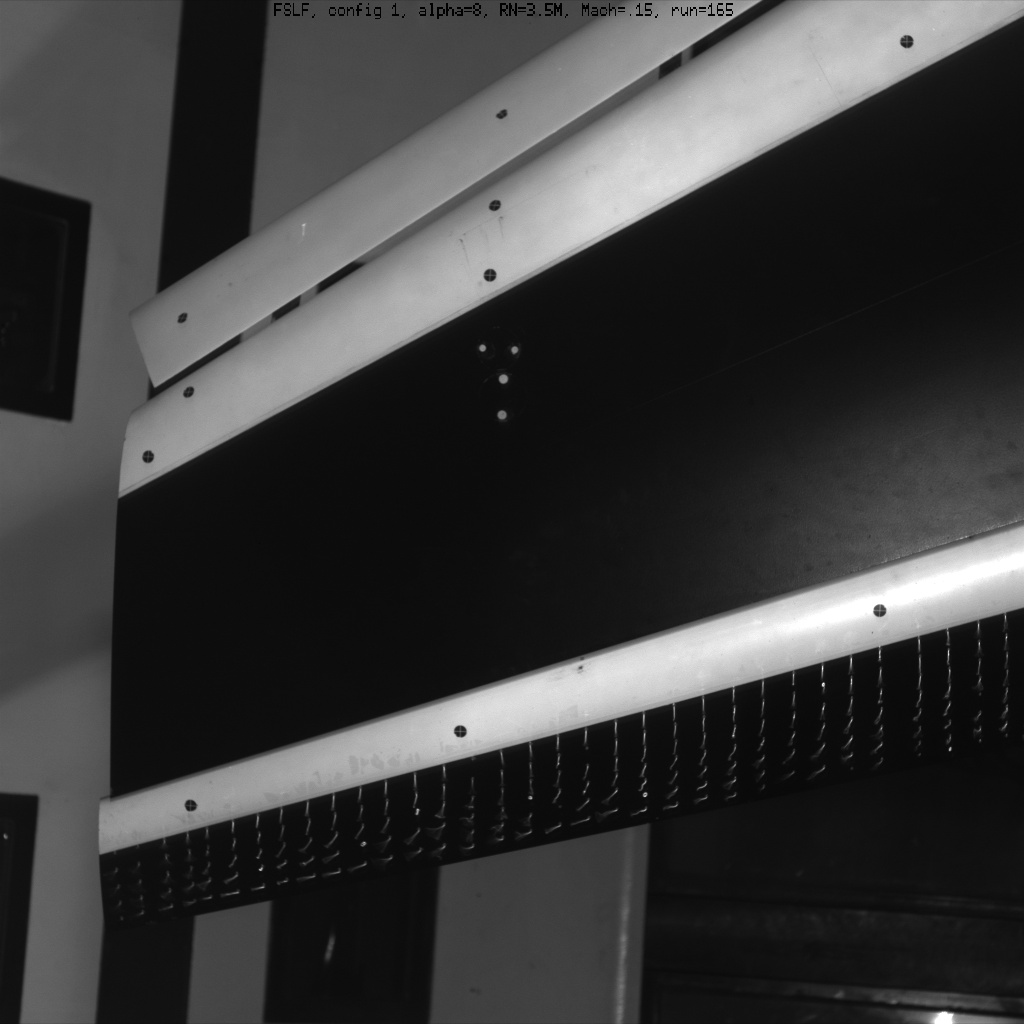
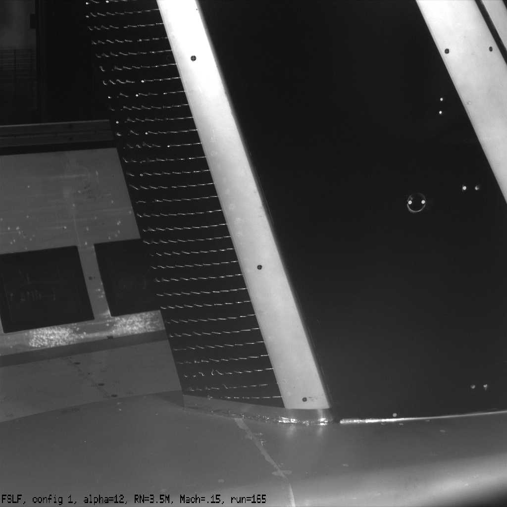
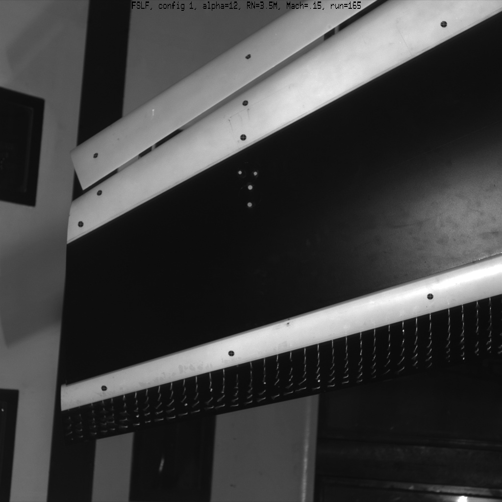
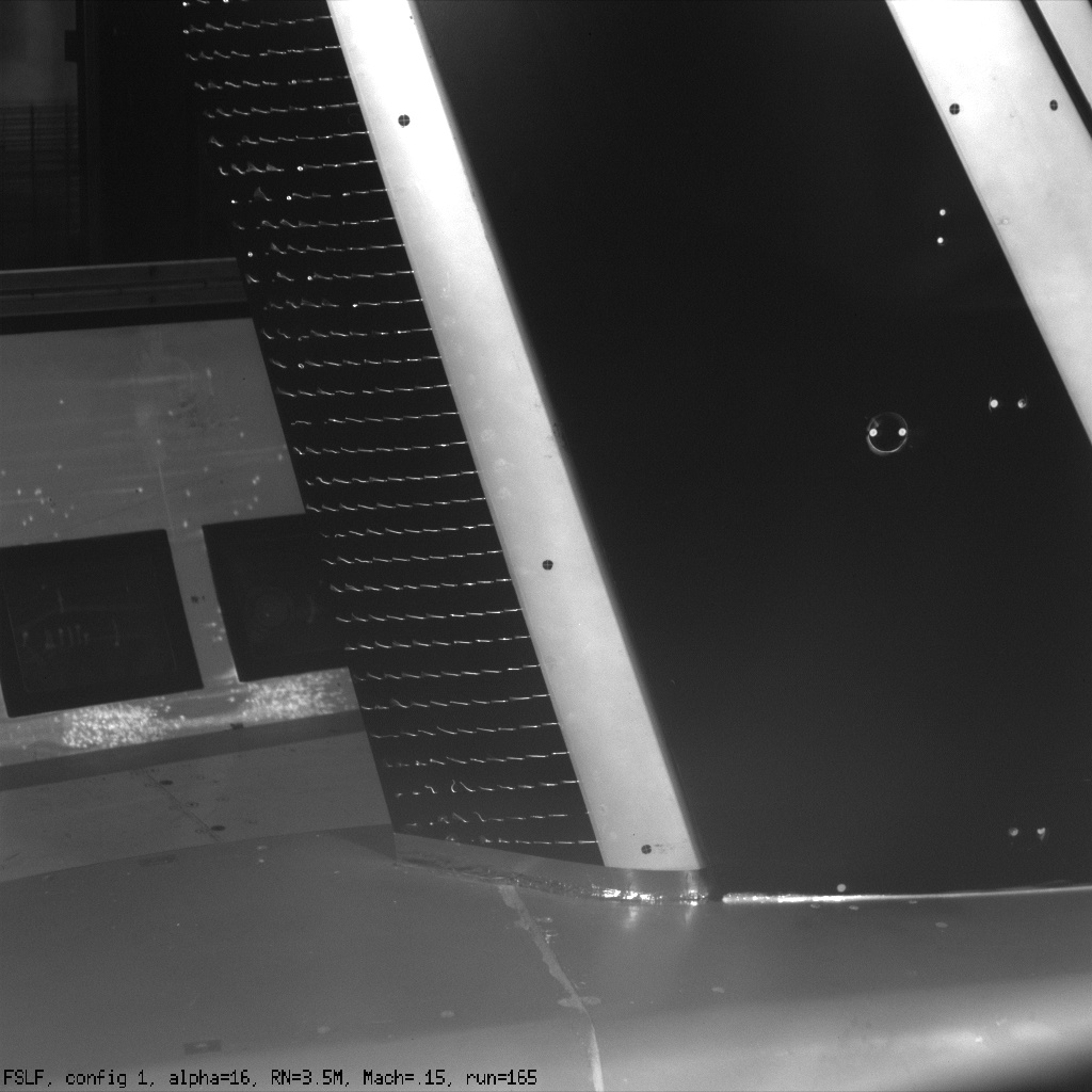
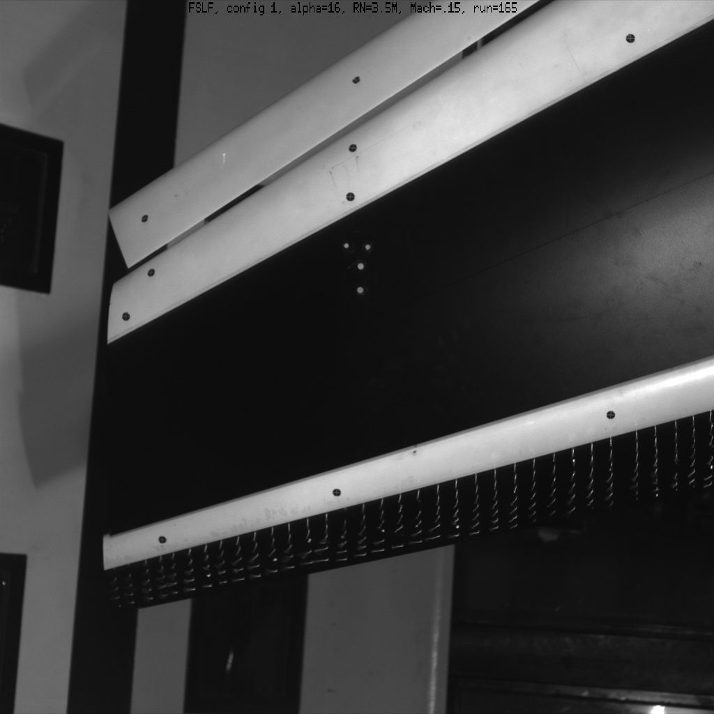
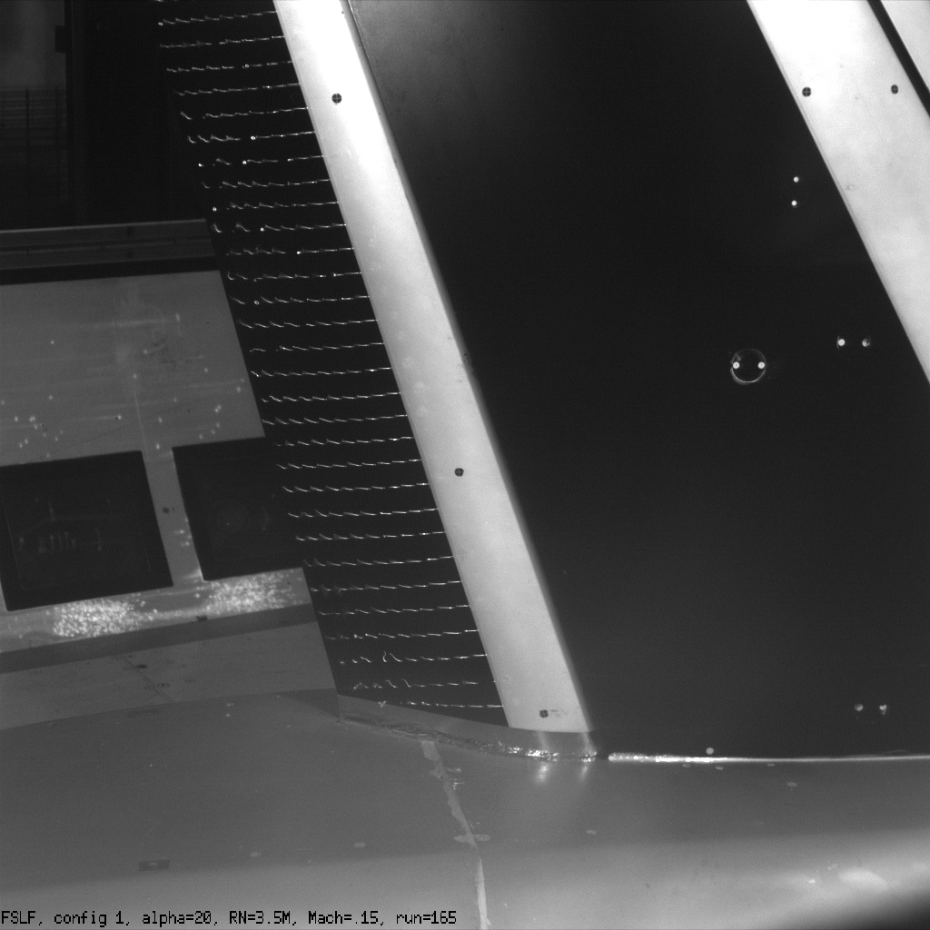
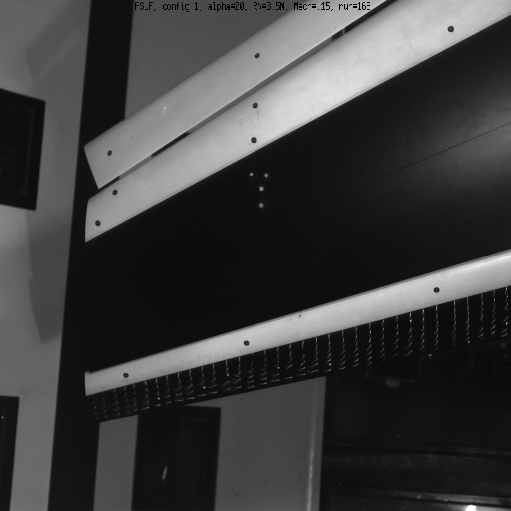
Some Trap Wing mini-tuft images for Config 1 (slat 30, flap 25) are given on this page. These are from
the NASA Ames 12 Foot Pressure Tunnel Test 60. This test was conducted in early 1999.
Several caveats:
- These images are from a different tunnel than other experimental data provided on this site.
- These images are also at somewhat different conditions: they are for
Mach=0.15 and Reynolds numbers of 3.5 million (run 165).
- The alpha given in each image is the uncorrected alpha, i.e. wall corrections
have not been applied to the angle-of-attack number printed in the photo.
The corrected alpha is listed above each photo.
These images should be used only to gain a qualitative sense of
the state of the near-surface flowfield over the flap for the particular
workshop cases.
Corrected angle-of-attack = 1.8 deg:
Corrected angle-of-attack = 6.5 deg:
Corrected angle-of-attack = 11.0 deg:
Corrected angle-of-attack = 15.5 deg:
Corrected angle-of-attack = 20.0 deg:
Corrected angle-of-attack = 24.0 deg:
These images have been compressed to fit on the web page.
To see larger images, download the following
(tarred gzipped) directory containing these jpg files:
TuftImages.tar.gz, and view them using your
own software.
Return to: Experimental Data Top Page
Return to: High Lift Prediction Workshop Home Page
Page Curator and NASA Official Responsible for Content
Li Wang
Last Updated
July 28, 2011
Privacy Act Statement
Accessibility Statement


