EXPERIMENTAL DATA: Velocity Probes
1st
AIAA CFD High Lift Prediction Workshop
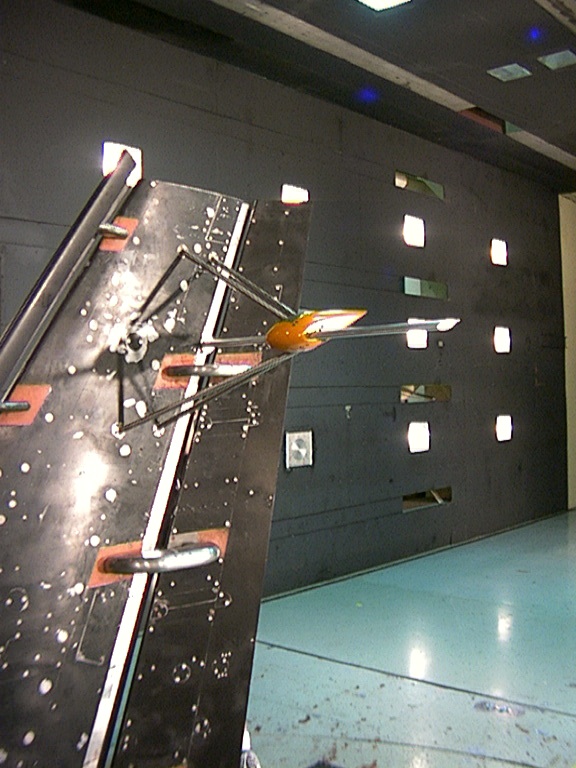
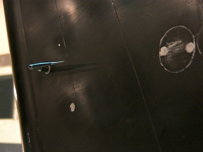
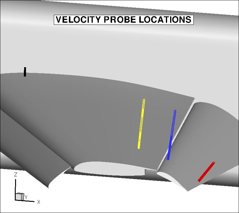
A limited amount of velocity probe experimental data from the 14x22 test are given
below. These were taken using a 7-hole probe, and are given at 2 locations on the flap (83% span), and 2 locations
on the main element (15% span and 83% span). Data are only available for Configuration 1 for corrected angles of attack of
approximately 10 deg, 20 deg, and 28 deg (the latter angle is one of the cases from the Workshop).
7-hole Probe Data:
(be sure to scroll to the bottom of the page for important information about probe data over the flap!)
Configuration 1, alpha=10 deg:
Configuration 1, alpha=20 deg:
Configuration 1, alpha=28 deg:
NOTES:
- There were differences noted in the flap position between the 1998/1999 and 2002/2003 tests
(for details, see: AIAA Paper 2011-862). The sensitivity of the forces and moments to the flap overlap discrepancy
was expected to be small. (The slat and main element positions were the same.)
- It is unknown what the effect of the different flap overlaps has on the
viscous phenomena of the flow field. The experimental data can still be used
as a guide, but caution should be applied when making any comparisons
between CFD and experiment.
- The 7-hole probe data (above) are relative to the 1998/1999 flap position, while the CFD flap definition used
throughout the HiLiftPW workshop were from the 2002 QA measurements.
- This means that the x, y, z flap probe positions given in the data files above will appear slightly
shifted relative to the CFD definition of the flap. This is because, as stated above, the
probe positions are relative to the 1998/99 flap position and not the position of the flap used
in the CFD grids. Although the location of the flap was different for these velocity profile data
sets, it is important to note that the slat and main element positions of the velocity profile data
set are the same as the CFD positions. I.e., the x, y, z positions of the flap probes are correct
relative to the upstream slat and main elements.
- Recommendation: if focusing on comparisons with slat and main element wakes over the flap, then use
the original experimental data over the flap as given above. If focusing on comparisons with the flap boundary layer, then use the data below (shifted and rotated to be relative to the 2002 QA flap position).
Shifted Flap Data to account for different 2002 QA flap position:
Configuration 1, alpha=10 deg:
Configuration 1, alpha=20 deg:
Configuration 1, alpha=28 deg:
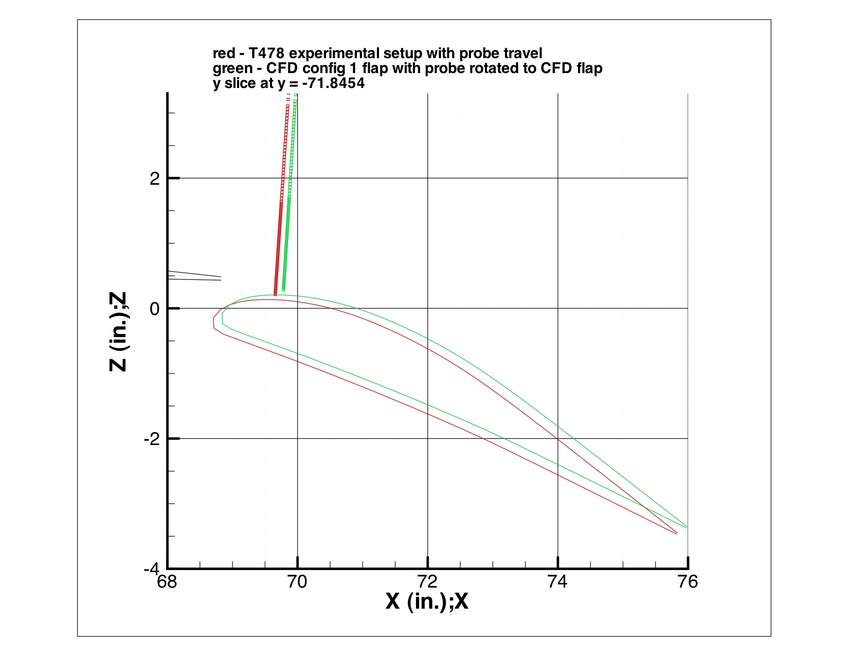
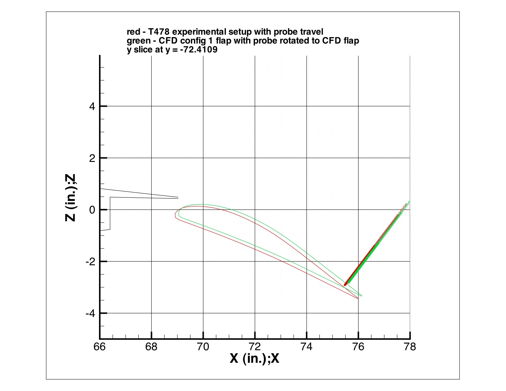
Plots are shown below comparing the 2 flap positions (at span station near y=-72): red shows the 1998/1999 flap position
and the corresponding 7-hole probe locations; green shows the 2002 QA flap position (used by CFD for the workshop) and the shifted probe
locations relative to that position.
Return to: Experimental Data Top Page
Return to: High Lift Prediction Workshop Home Page
Page Curator and NASA Official Responsible for Content
Li Wang
Last Updated
October 14, 2011
Privacy Act Statement
Accessibility Statement
