14x22-FOOT TUNNEL WALL INFORMATION
1st
AIAA CFD High Lift Prediction Workshop
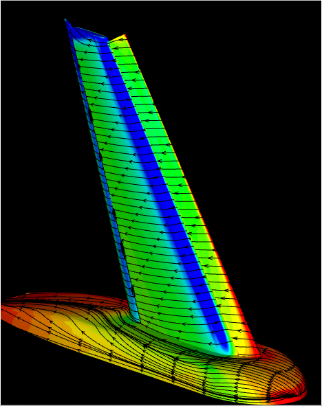
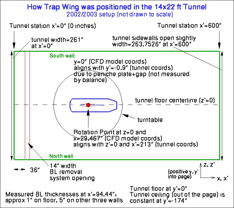
The Trap Wing was mounted on the floor of the 14x22-foot wind tunnel (NASA LaRC). Details for Configuration 1 in
the 2002/2003 setup are given in
the following figure (flow is from left to right):
This figure can be downloaded as a pdf file:
walls4.pdf.
The model was mounted on a turntable (of diameter 189 inches, centered at tunnel
station x'=213 inches), in order to change angle of attack.
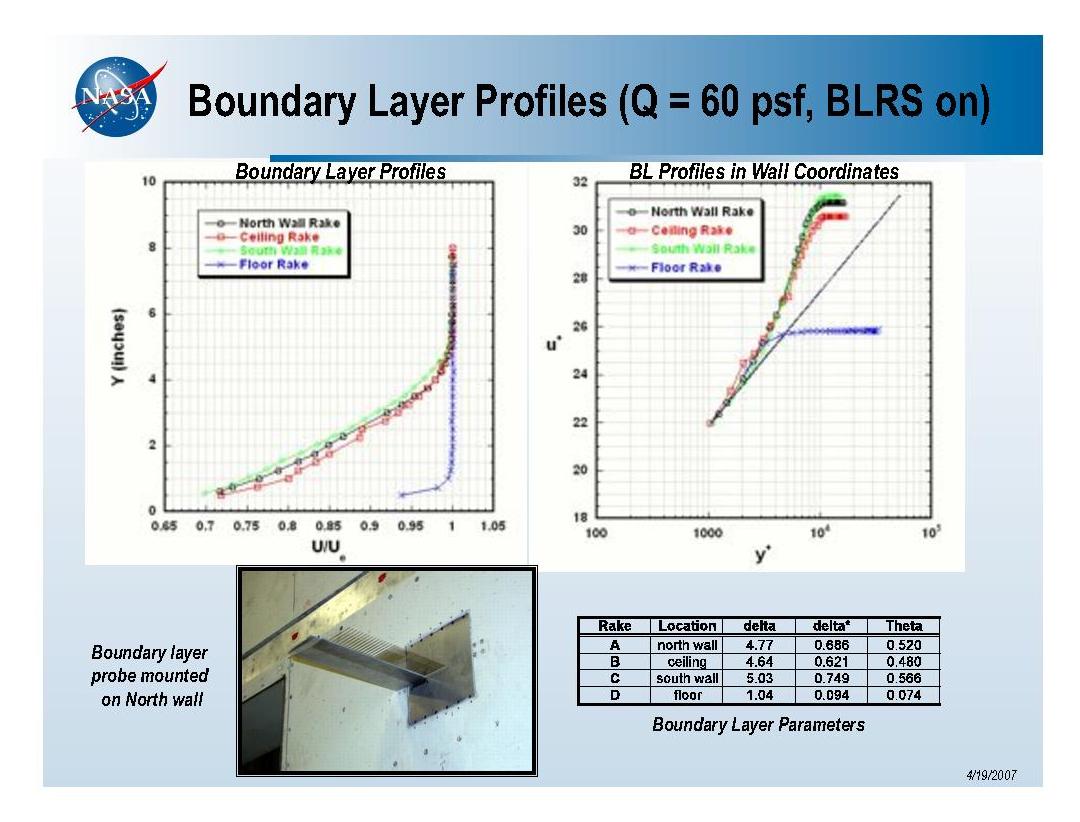
The floor of the tunnel had a boundary layer removal system (BLRS) on the floor upstream of the
model, which reduced the height of the incoming boundary layer.
Note that in earlier tests (for example, ones that tested Configuration 8), the model was
mounted in a different position (further forward) on the turntable.
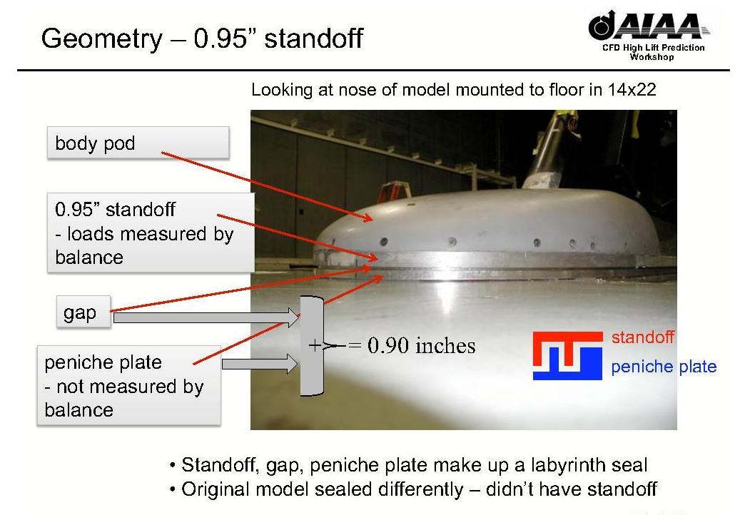
Other relevant figures are provided below:
Other tunnel-related information: The turbulence intensity in the 14x22-foot tunnel has been documented to be
between about Urms/U=0.06% (at low Q) and 0.09% (at Q near 100 psf).
For the workshop
conditions (approx. 60 psf, BLRS on, new suction surface) the turbulence intensity was between 0.07% - 0.08%.
For additional information, see: NASA TP-2004-213247, "Free-Stream Turbulence Intensity in the
Langley 14- by 22-Foot Subsonic Tunnel," by D. H. Neuhart and C. B. McGinley, 2004.
Return to: Experimental Data Top Page
Return to: High Lift Prediction Workshop Home Page
Page Curator and NASA Official Responsible for Content
Li Wang
Last Updated
December 14, 2011
Privacy Act Statement
Accessibility Statement


