FREQUENTLY ASKED QUESTIONS
2nd
AIAA CFD High Lift Prediction Workshop
Q1: When will the website provide the geometries, grids, data,
testcases, data submittal forms, etc. for HiLiftPW-2?
A1: As of the beginning of November 2012, much of this
information is now in place. Grids are expected to be available by early 2013 (see "Tentative Dates" on the
Home Page). The website will continue to be populated over time as
various pieces of information become available. You are encouraged to ask to be included on the
HiLiftPW email distribution list, for notification of major updates.
Email:
hiliftpw@gmail.com.
Q2: What happened at the first workshop (HiLiftPW-1)?
A2: The first HiLift workshop took place in June 2010. See
Webpage for HiLiftPW-1 for detailed information.
Q3: Where can I find more information about the experimental
data for HiLiftPW-2?
A3: Please see the talk presented by
Ralf Rudnik of DLR at the 30th AIAA Applied Aero Conference,
June 25-28, 2012, New Orleans LA:
14-Rudnik-hilift.pdf.
This was published as paper number AIAA-2012-2924,
which is available on the
Additional Experimental Information page.
Q4: Is there a list of references
that are relevant to HiLiftPW-1 (Trap Wing) and HiLiftPW-2 (DLR F11)?
A4: Some
known references are listed in the following document:
HighLiftWorkshopPublications2012 (pdf file).
Q5: What does the following statement mean:
"simulations are free air, and no wind tunnel walls or model support systems are to be included"?
A5: It
is expected that the half-model (as defined in the CAD) be computed with symmetry boundary
conditions on the symmetry plane and farfield boundary conditions at the outer boundaries,
thus simulating a full configuration with zero sideslip angle in "free air." The CFD
results are being compared to experimental wind tunnel data that have been corrected to remove
wall effects.
Q6: Do the experimental forces and moments
include the body as well as the wing?
A6: Yes, the body is
included in the determination of forces and moments via an internal balance. The
split is at the labyrinth seal between the fuselage and peniche (the peniche
is not accounted for).
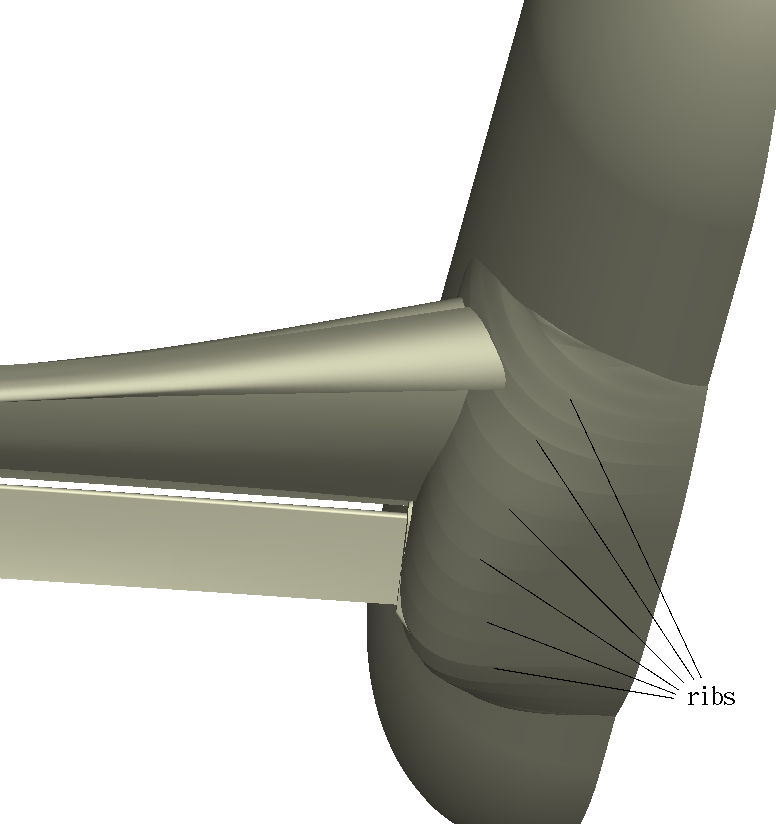
Q7: There are noticeable "ribs" in the posted geometry
on the DLR F11 wing-body fairing. Are these real? Will they cause problems?
A7: These minor C2-discontinuities present in
the posted geometry files do not reflect the actual model. However, given the location and likely low relevance
of the discontinuities, repairing the geometry in this area has not been deemed necessary for this workshop.
Q8: How rigid are the gridding guidelines?
A8: The gridding guidelines, which can be found on the
Grids page, have been distilled from the best practices of past workshops. As such,
they are to be taken as guidelines, and not as strict rules.
Many grid generators may find it difficult or impossible to adhere to all
of the guidelines. When making your own grids, the most important thing is to document
details of what was done.
Q9: Can you explain the differences between Config 2,
Config 4, and Config 5?
A9: The various configurations are
successively more accurate representations of the actual wind tunnel geometry. Config 2
only includes the body, slat, main, and flap (along with a flap seal). There are no slat tracks
or flap track fairings in Config 2.
Config 4 is the same as Config 2, but it further includes the slat tracks and flap track fairings.
Config 5 is the same as Config 4, but it further includes slat
pressure tube bundles, which lay alongside the slat tracks
and hence are exposed to the airstream. It is one of the goals of this workshop to explore
the effects of successively improving the geometric fidelity of the CFD.
Config 5 is sometimes referred to as the "full" configuration, in the sense that "full"
means "best of the three approximations to the actual wind tunnel configuration".
Note that in all cases, a half-geometry with symmetry boundary conditions on the
symmetry plane are to be used, along with farfield boundary conditions at the
outer boundaries (see Q5/A5 above).
Q10: Can someone with a point-matched structured grid code
participate in the workshop, even though no committee-supplied grids are provided for required
Case 2 (Config 4)?
A10: Yes. As stated in a footnote
in the test case description, the committee is not providing point-matched structured grids for Case 2.
Therefore, Cases 2a and 2b are optional for participants with point-matched structured-grid codes.
Those participants would only be required to submit results for Case 1.
Q11: Why are CFD velocity data being collected
at both low and high Reynolds number conditions, when there are only PIV data at low Re?
A11: We will be comparing
CFD velocity results at low Reynolds number to the experimental PIV data. But also we would like to see the effect
of changing the Reynolds number on the CFD velocity profiles. We can compare the various CFD results
against each other.
Q12: We are making our own grids. What is the deadline
for uploading them to the committee?
A12: Grids created by workshop
participants should be uploaded to the HiLiftPW ftp server prior to the workshop. Contact the page
curator or hiliftpw@gmail.com for login/access details.
Q13: What do I need to do to attend the workshop?
A13: To attend the workshop, both participants
and non-participants must register for HiLiftPW-2 with AIAA: see
HILIFTPW-2 Registration (AIAA).
AIAA also gives details regarding travel and accomodations, visas, etc. Note that registering for the
Fluids, Plasma, Thermophysics, Applied Aero, CFD, Atmospheric & Space, or Ground Testing conference alone
does not give you access to HiLiftPW-2 (and vice versa). You must specifically register for HiLiftPW-2,
and pay its additional registration fee. If you are a participant, you must submit an abstract and data
submittal forms by the deadlines listed on the
High Lift Prediction Workshop Home Page, and you must
prepare slides for an oral presentation to be given at the workshop (there is no written paper).
Q14: Please describe how to obtain lift coefficient
(CL), drag coefficient (CD), and pitching moment coefficient (CM)
for the HiLiftPW-2 configuration.
A14: Lift coefficient is defined
as L/(qS), where L is the sum of the components of the pressure forces and viscous forces on
all parts of the vehicle in the UP
direction, taking into account the angle-of-attack.
Because the workshop configuration is a half-model, there is no yaw to consider here.
The q=dynamic pressure=0.5*rho_inf*U_inf2, and S is the planform area
(=419130 mm2 in the current case for the half-model).
Similarly, drag coefficient is defined
as D/(qS), where D is the sum of the components of the pressure forces and viscous forces on
all parts of the vehicle in the DOWNSTREAM
direction, taking into account the angle-of-attack.
Moment coefficient is defined as M/(qSc). Here, M is the moment about the moment reference
center (MRC): x=1428.90 mm, y=0.0 mm, z=-41.61 mm, and c is the MAC=347.09 mm. This workshop is
asking for pitching moment, which is moment about the y-axis pointing out of the MRC.
To get M, you need to sum up all of the local forces (pressure forces and viscous forces)
times their moment arm about the MRC's y-axis.
By convention, CM is positive when it acts to pitch the aircraft nose UP.
Return to: High Lift Prediction Workshop Home Page
Privacy Act Statement
Accessibility Statement
Responsible NASA Official:
Li Wang
Page Curator:
Li Wang
Last Updated: 05/14/2013


