skip to content

DATA SUBMITTAL FORMS & POSTPROCESSING INFO

3rd AIAA CFD High Lift Prediction Workshop


Logo 3 for HiLiftPW-3 Logo 1 for HiLiftPW-3 Logo 2 for HiLiftPW-3 Logo 4 for HiLiftPW-3


Data Submittal Forms

The following Tecplot-readable Data Submittal Forms are to be used for submittal to HiLiftPW-3:

Download all Data Submittal Forms in a tarred, gzipped directory:
XXX_Lastname_Code_Model_v1.tar.gz (minor typo revision to a few comment lines only on 04/11/2017 and to unimportant DATASETAUXDATA lines only on 04/26/2017)

Instructions:

All CFD data should be given in deployed (un-stowed) coordinates (i.e., directly from the grids as computed). If participants analyzed additional conditions not asked for, they are encouraged to include them in the data submittal if desired.


Postprocessing: Surface Data Extraction for HL-CRM (Case 1)

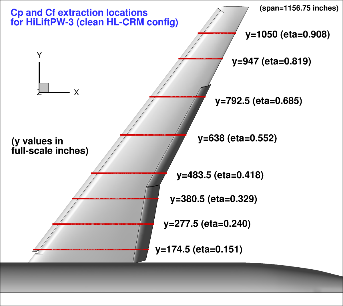
Surface data extraction of Cp and Cf for HL-CRM is simply along y=constant cuts. See the following figure:
Surface extraction locations for HL-CRM

Note that the HL-CRM configuration is defined in the +Y plane, in inches.

For those participants with access to Tecplot, a macro file is provided here that can be used to extract data on the surface at all of the requested pressure tap locations: HiLiftPW-3.HLCRM-SectionalCutter_v2.mcr Some editing will be required... see instructions inside the file.

IMPORTANT NOTE: We have used y=constant cuts here simply because experimental data does not exist for the HL-CRM for this workshop. When experimental data are eventually taken they will NOT lie along y=constant lines for the slat and flap in their deflected positions! Typically, in experiments on high lift configurations, the rows of pressure taps lie along straight lines in cruise position only (see, e.g., details under Postprocessing: Surface Data Extraction for JSM below).


Postprocessing: Velocity Data Extraction for HL-CRM (Case 1)

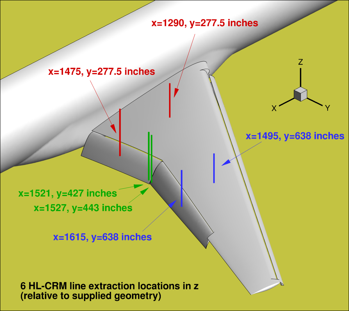
Velocity profile extraction for HL-CRM is along 6 different lines in the z-direction, as shown below. Note that x is aligned with the fuselage (x is NOT aligned with the freestream velocity vector except at alpha=0).
Velocity extraction locations for HL-CRM


Postprocessing: Surface Data Extraction for JSM (Case 2)

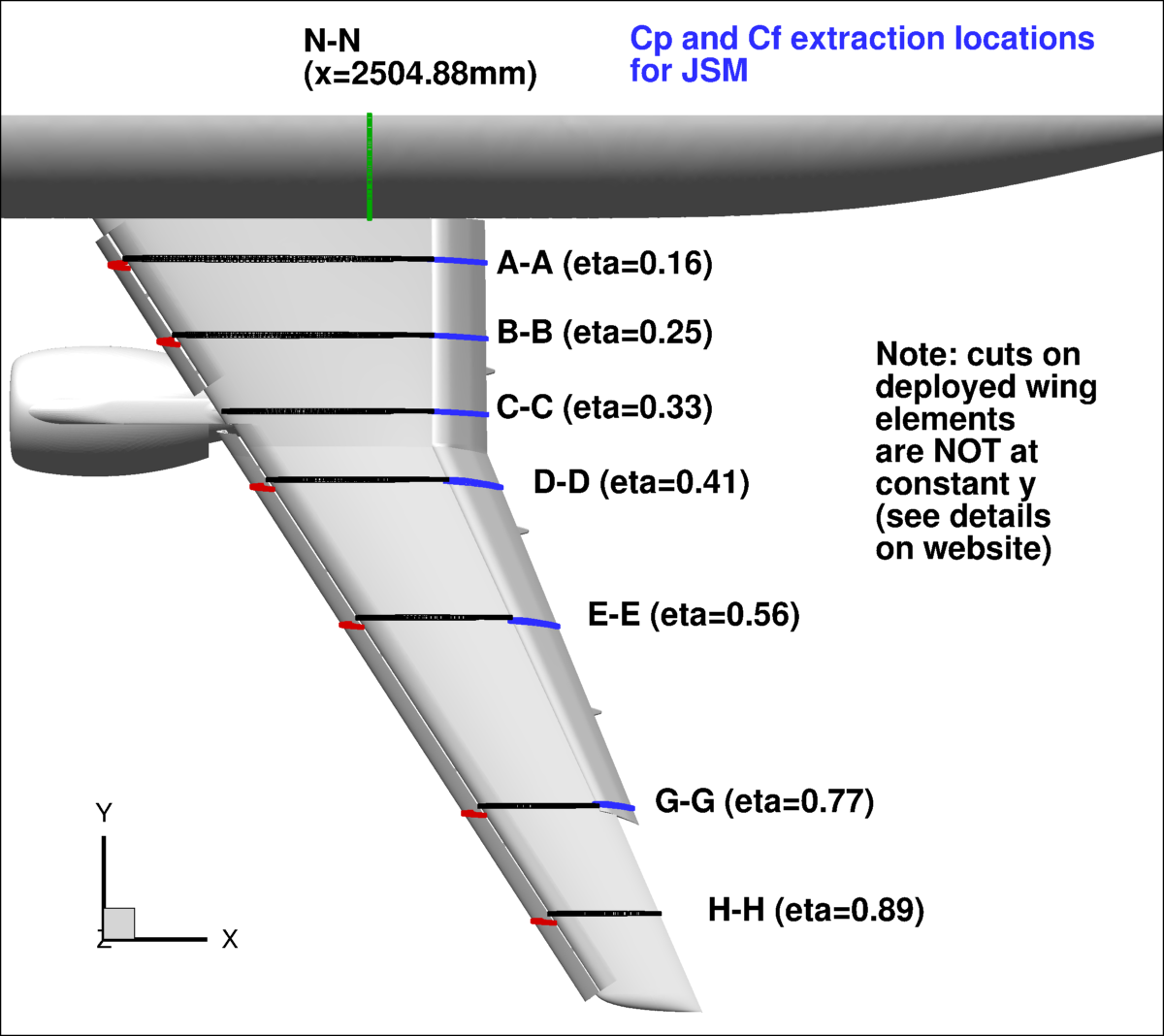
For this case, the pressure tap rows are not aligned on all 3 elements. The following figure shows the location of the extraction planes:
Surface extraction locations for JSM

Note that the JSM configuration is defined in the -Y plane, in mm. The following text file defines planar cuts that intersect the pressure taps for the 7 span stations on the main wing, slat, and flap when in deployed position: CuttingPlane_JSM_v2.txt.

For those participants with access to Tecplot, a macro file is provided here that can be used to extract data on the surface at all of the requested pressure tap locations: HiLiftPW-3.JSM.SectionalCutter_v2.mcr (updated 03/29/2017) Some editing will be required... see instructions inside the file. Note that while the above file CuttingPlane_JSM_v2.txt provides equations for the planes that cut the wing elements, the macro instead provides a point in each plane plus plane normal vector.


Postprocessing: Velocity Data Extraction for JSM (Case 2)

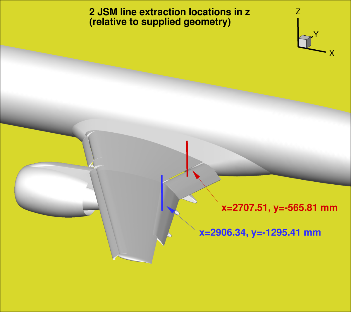
Velocity profile extraction for JSM is along 2 different lines on the flap in the z-direction, as shown below. Note that x is aligned with the fuselage (x is NOT aligned with the freestream velocity vector except at alpha=0).
Velocity extraction locations for JSM


Suggested Areas of Flow Solution Postprocessing

In addition to the requested data, participants are encouraged to report other comparisons or things learned during their investigation. For example, issues related to side-of-body separation, trailing-edge separation, edge or tip vortices, unsteady flow, transition, comparisons on the fuselage or on the nacelle/pylon, analysis of component forces on individual elements, etc. are all welcome.
 

Participants who are speaking at the workshop are asked to use the following presentation template as a guide:
 

Return to: High Lift Prediction Workshop Home Page


Recent significant updates:
07/15/2019 - Added note that surface pressures will NOT be along y=constant lines when the HL-CRM experiment is eventually conducted
04/26/2017 - Minor typo revision to unimportant DATASETAUXDATA lines of the case3_iterative_v1.dat data submission file
04/19/2017 - Clarification (under Instructions) about where to extract velocities; also how x points; updated JSM velocity picture so lines easier to see
04/15/2017 - Added presentation template for the workshop
04/11/2017 - Minor typo revision to one comment line of the case2x_vel_v1.dat data submission files
03/30/2017 - Clarification about reference or freestream velocity
03/29/2017 - Updated the Tecplot macro: HiLiftPW-3.JSM.SectionalCutter_v2.mcr to include INFO

Privacy Act Statement

Accessibility Statement

Responsible NASA Official: Christopher Rumsey
Page Curator: Christopher Rumsey
Last Updated: 07/15/2019