
MAIN ATTACHMENT LINE LOCATIONS & DISCUSSION
1st
AIAA CFD High Lift Prediction Workshop
Main Attachment Line
The attachment line on the main element is determined following
the same method for the slat.
The procedure is complicated by the wake of the slat
interacting with the flow around the main element. The main element
had nine rows of pressure taps that covered the entire chord. These
were at eta = 0.17, 0.28, 0.41, 0.50,
0.65, 0.70, 0.85, 0.95, 0.98. Eta is the
non-dimensionalized span wise coordinate and is equal to Y / 85.059 in.
(the span of the model).
The accuracy of estimation of the attachment line location
is dependent on the number and position of the pressure taps on the
model, among other factors. The uncertainty of the attachment line location
with respect to port placement is discussed
here.
On the Main element the computation of the attachment line
locations is also complicated by the wake emanating from the slat and three
dimesional effects of the brackets. Note that one of the assumptions
in the method of determining the attachment line location is infinite swept
wing; the three dimentional effects of the brackets and the wake of the
slat would violate that assumption.
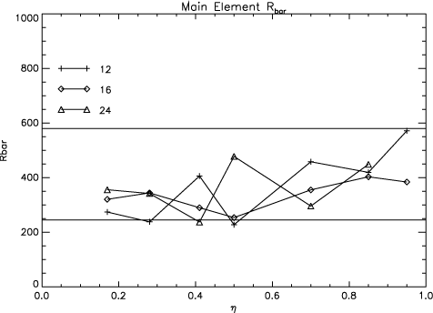
View the values of Rbar for 12,16, 24 degrees
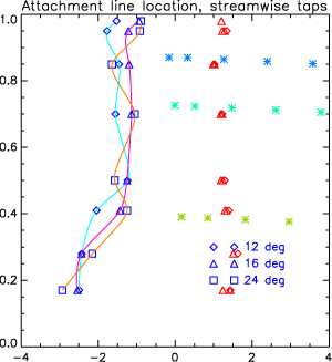
View the locations of the attachment lines versus the spanwies coordinate eta
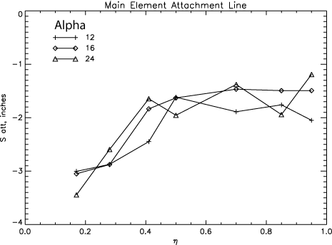
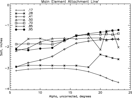
View the variation of the attachment line versus Alpha.
View the relative locations of the attachment line, upper surface films, and the suction peak
Return to: Main Notes Top Page
Return to: Transition Notes Top Page
Return to: Transition Information Top Page
Return to: Experimental Data Top Page
Return to: High Lift Prediction Workshop Home Page
Page Curator and NASA Official Responsible for Content
Li Wang
Last Updated
August 15, 2011
Privacy Act Statement
Accessibility Statement