skip to content

DATA SUBMITTAL FORMS & POSTPROCESSING INFO

2nd AIAA CFD High Lift Prediction Workshop


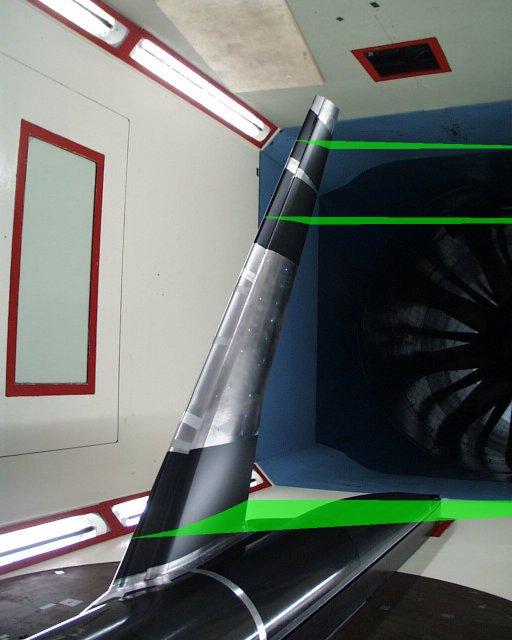
Logo for HiLiftPW-2 F11 model in wind tunnel, showing laser light sheets


Data Submittal Forms

The following Tecplot-readable Data Submittal Forms are to be used for submittal to HiLiftPW-2:

Download all Data Submittal Forms in a tarred, gzipped directory:
XXX_Lastname_Code_Model_v2.tar.gz (last modified 3/28/2013)

Instructions:

All CFD data should be given in deployed (un-stowed) coordinates (i.e., directly from the grids as computed). If participants analyzed additional alphas, they are encouraged to include them in the data submittal if desired.


Postprocessing: Surface Data Extraction

Recall that the slat and flap settings in the landing configuration (slat 26.5 deg, flap 32 deg) are such that the pressure tap rows on those devices are not along y=constant planes. For those participants with access to Tecplot, macro files are provided here that can be used to extract data on the surface at all of the locations where pressure taps are located. Note that the pressure and skin friction Data Forms ask for data in the following order: X, Y, Z, CP, CF, CFX, CFY, CFZ (where CF, CFX, CFY, and CFZ should be given the value -999 if they are not being provided). Use these macros by performing the following steps for each of the cases run:
  1. Load (into Tecplot) a data file containing the solid walls along with your CFD solution on the walls. Be sure that X, Y, and Z are in millimeters. Check to see that Tecplot can read your data correctly.
  2. These macros are for the half-plane geometry defined in the +Y direction; therefore if your geometry lies only in the -Y sector, you must first flip or mirror your data (e.g., using Data-CreateZone-Mirror-XZPlane).
  3. If CP is not one of your solution variables, then use Tecplot to create it.
  4. If you plan to include the optional CF, CFX, CFY, and CFZ, then make sure these are defined and available. If not, then use Data-Alter-SpecifyEquations to create new variables with the value -999 (e.g., {cfx}=-999).
  5. Then, run the macro extractplanes.mcr. It will create 30 new zones of extracted data at all the cuts asked for, in the desired order.
  6. Under Data-Delete-Zone, delete all original zones so that only the 30 newly created zones are left.
  7. Pick the appropriate renaming macro (e.g., renamezones_case1.mcr for case 1). Edit it to replace "?" with the angle-of-attack and (for case 1 only) replace "%%%%%" with "coarse", "medium", or "fine". Also replace XXX with your assigned participant ID.
  8. Run the renaming macro. This renames each of the cuts appropriately.
  9. These cuts can then be written out by the user to an ASCII file (use point format); write out the variables X, Y, Z, CP, CF, CFX, CFY, and CFZ (in that order... this is the order defined in the data submittal form).
  10. The zones from this file should then be relatively easy to include into the Data Forms. If you can limit the extractions to occur only on the appropriate elements, then do so. But if the extraction process also extracts unneeded areas (e.g., if the extraction along the slat also includes data on the main and flap), then do not worry... these areas will be ignored.

extractplanes.mcr
renamezones_case1.mcr
renamezones_case2a.mcr
renamezones_case2b.mcr
renamezones_case2c.mcr
renamezones_case3a.mcr
renamezones_case3b.mcr

(Created with Tecplot 360 builds 14 and 12. Note, if you have an earlier version of Tecplot, the macros may still work if you modify the 1st line in the macro.)

If you do not have access to Tecplot, the following description may be helpful for defining planar cuts on the slat and flap: SlatFlapPositionDescription.pdf.


Postprocessing: Velocity Data Extraction
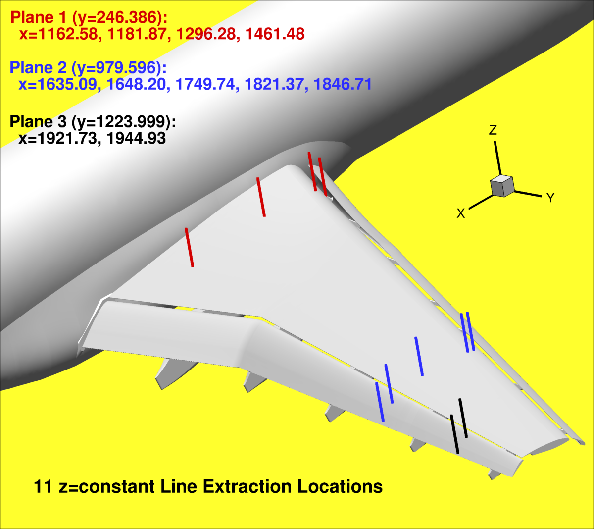

3D view of all PIV windows

You can use the file: extract_lines_forvelocity.dat (last modified 3/28/2013) along with Tecplot's interpolation capability to extract velocity as follows:
  1. If it is not too large, bring up your volume solution file in Tecplot (Initial Plot Type = 3D Cartesian). If it is too large, first output the planes y=246.386, y=979.596, and y=1223.999 and bring those planes up in Tecplot (Initial Plot Type = 2D Cartesian, then Plot -> Assign XY -> choose X and Z). Be sure that X, Y, and Z are in millimeters, and that your volume file or your planes are in the +Y sector. Check to see that Tecplot can read your data correctly (problems have been noted when reading some PLOT3D files output by Overflow).
  2. If u/Uinf, v/Uinf, and w/Uinf are not among your solution variables, then use Tecplot to create them. For example, click Data -> Alter -> Specify Equations. Then type the equations to create the appropriate variables. For example, if your solution stores PLOT3D conserved nondimensional variables, then:
    • {u/Uinf} = {RHO-U}/{RHO}/0.175
    • {v/Uinf} = {RHO-V}/{RHO}/0.175
    • {w/Uinf} = {RHO-W}/{RHO}/0.175
    Click the Compute button.
  3. Load the file extract_lines_forvelocity.dat (File -> Load Data File(s) -> Tecplot Data Loader -> Add to current data set).
  4. Using Data -> Interpolate -> Linear, do the following:
    • If you are working from the volume solution file, select all source zones and interpolate (one click at a time) to each of the 11 Destination Zones (these are the 11 defined lines from the extract_lines_forvelocity.dat file). Click "Compute" once for each of the 11 Destination Zones.
    • If you are working from 3 planar files, (1) select the Y=246.386 plane ONLY in the Source Zone, then interpolate (one click at a time) to the 4 different p1 Destination Zones; (2) select the Y=979.596 plane ONLY in the Source Zone, then interpolate (one click at a time) to the 5 different p2 Destination Zones; (3) select the Y=1223.999 plane ONLY in the Source Zone, then interpolate (one click at a time) to the 2 different p3 Destination Zones.
  5. Bring up the "Write Data File Options" dialog box by using File -> Write Data File.
  6. Click "ASCII" and "Point".
  7. Highlight ONLY the 11 Destination Zones on the left of the pane.
  8. Highlight X, Y, Z, u/Uinf, v/Uinf, and w/Uinf on the right of the pane.
  9. Click "OK" to write a file.
  10. Open the newly written file and edit all of the ZONE information (replace "#" with the case number 1, 2a, 2b, 2c, 3a, or 3b, replace "?" with the angle-of-attack, replace "%%%%%" with "medium", or "fine", and replace XXX with your assigned participant ID).

If you do not have access to Tecplot, extract the velocity components along the specified 11 vertical lines using your own data extraction technique. Be sure to include a sufficient number of interpolant points in order to define the velocity profiles adequately. For example, use the endpoints defined in the file: extract_lines_forvelocity_endptsonly.dat and include approximately 300 evenly-spaced points inbetween.
 

Return to: High Lift Prediction Workshop Home Page


Privacy Act Statement

Accessibility Statement

Responsible NASA Official: Li Wang
Page Curator: Li Wang
Last Updated: 04/10/2013
(minor parenthetical note about 1st line in Tecplot macro files)
(new note regarding when to submit results in separate directories)