GEOMETRY FILES
5th
AIAA CFD High Lift Prediction Workshop
The configuration used in HLPW-5 is again the
NASA High-Lift Common Research Model (CRM-HL). A general description of the CRM-HL can be found in
AIAA Paper 2020-2771 (Lacy & Clark).
Now, with expanded testing in the CRM-HL "ecosystem," there are often different areas of emphasis
each time an ecosystem partner conducts a wind tunnel test.
It is also important to note that the support hardware - such as slat brackets
and flap supports - sometimes require minor redesigns because of particular wind tunnel requirements.
As a result, for HLPW-5 there are multiple geometries being used. These geometries are different in their
details from the geometry used in HLPW-4. They are presented here for each of
the three HLPW-5 Test Cases. All are provided in full-scale inches.
Note that the last 2 inches (full scale) of the original CRM-HL fuselage geometry was purposefully cut off in the CAD files,
to avoid problematic curvature that could cause issues for some CFD methods. Thus, the CAD fuselage length is
very slightly different from many of the built CRM-HL models. This very minor change has no effect
on any of the results of interest.
The reference geometry and tripping information for the CRM-HL can be found on the page:
https://commonresearchmodel.larc.nasa.gov/high-lift-crm/high-lift-crm-geometry/reference-geometry/. The tripping
details are given in the file named
"trip01r1.stp."
Although each particular model in the CRM-HL ecosystem
generally followed this tripping strategy, there may be some differences, as described in each section below.
Test Case 1: CRM-HL Wing-Body Verification
CRM-HL Wing-Body configuration (STP file):
- CRMHL_ReferenceSolid_WingBody_09222022.stp.zip
- The above CAD includes the farfield definition, which (for Case 1) should be a rectangular cuboid
with dimensions -65000 ≤ x ≤ 65000 inches, 0 ≤ y ≤ 65000 inches,
-65000 ≤ z ≤ 65000 inches.
CRM-HL Wing-Body configuration without the farfield boundary definition (STP file):
Test Case 2: Configuration Buildup
This test case is based on experiments
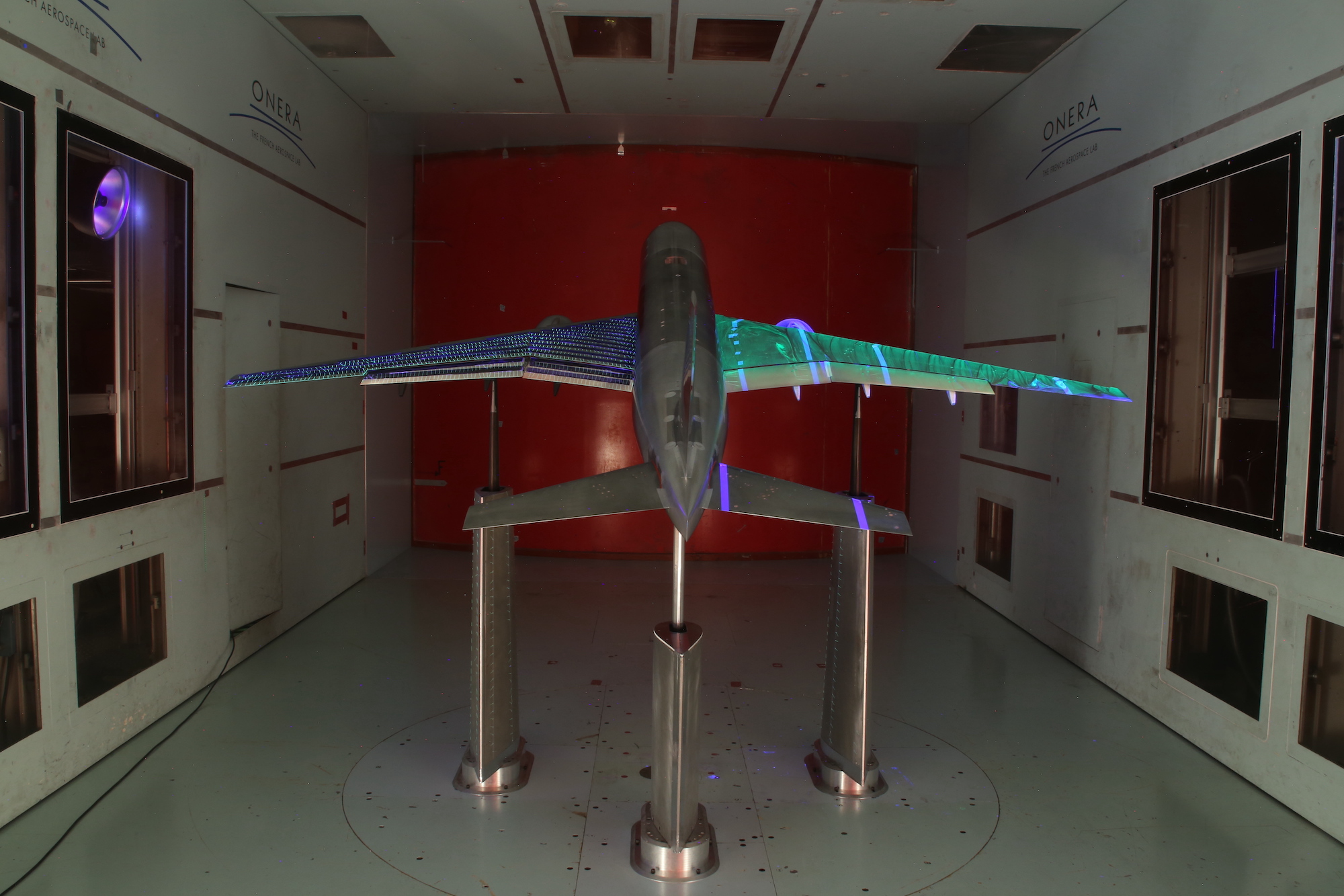
using two different models: the ONERA 1/19.5 (approx 5.1%)
configuration and the Boeing 6% configuration.
-
Note that the geometries for test cases 2.2 and 2.3 were
updated to Version 2 on 10/04/2023. A surface on the main element leading edge inadvertently had a fold where two surfaces connected.
Many grid generators were able to grid over the fold with no consequence. In those cases the existing grids are considered to be valid,
and there is no need to update the geometry.
Farfield Definition:
Farfield domain is preferred to be a hemisphere with distance 100*MAC,
although other similar "best practice" domain extents are allowed.
Tripping Information:
In the ONERA experiment (Test Cases 2.2, 2.3, and 2.4) tripping details can be found in the paper
AIAA-2023-0823.
The following is extracted (with permission of the authors) directly from AIAA-2023-0823:
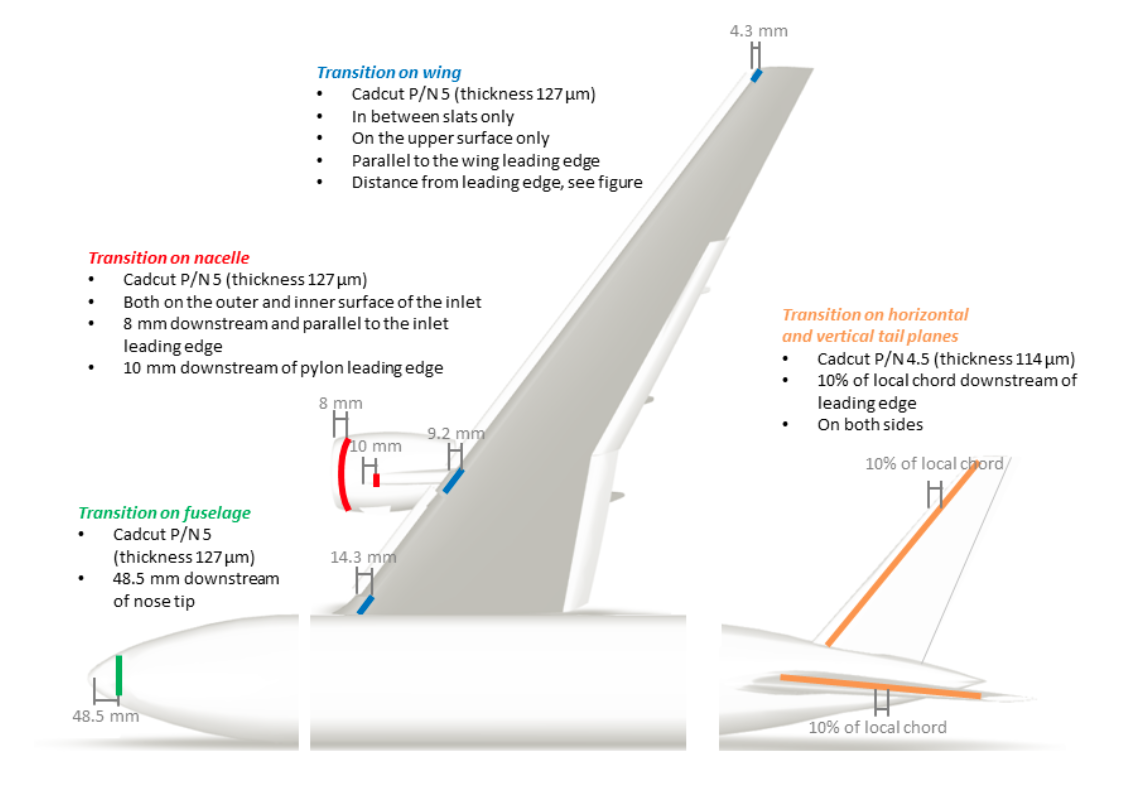
"The boundary layer transition was tripped using so-called 'cadcut' strips.
Each strip is glued on the model surface and consists in a row of circular dots of 1.27 mm diameter, placed every 2.54 mm. The
thickness of the dots for this test was 114 micro m on the empennages, and 127 micro m on the fuselage, wings and nacelles. This
thickness was selected in order to be comparable to the test in the Qinetiq 5m wind tunnel, once the difference in model scale
is taken into account. The location of the transition trips is indicated in Figure 3, with all dimensions given at model scale.
No tripping is applied on section of the wings where slats and flaps are present."
Figure 3 is replicated here, with permission of the authors:
The experiment for Test Case 2.1 (CRM-HL-WBHV) has not been conducted yet,
but it is planned to follow the tripping provided in
trip01r1.stp.
The trip dot sizes are planned to be the same as detailed in the
HLPW4 tripping information from QinetiQ test of 10% CRM-HL model.
Unofficial Case 2.2 geometry file for SPECIAL RANS investigation subsequent to HLPW-5:
The following geometry file has been ALTERED for the purposes of an auxiliary investigation into the effects of
the slat brackets on CFD results. This file is not a part of HLPW-5, and does not represent any real or built configuration.
Therefore, it should only be used with caution.
Test Case 3: Reynolds Number Study
This test case is based on experiments
using the NASA 5.2% configuration.
-
Farfield Definition:
Farfield domain is preferred to be a hemisphere with distance 100*MAC,
although other similar "best practice" domain extents are allowed.
Tripping Information:
For Test Case 3, the 5.2% model is tripped very similar to the description provided from the previous High Lift Workshop (see
HLPW4 tripping information from QinetiQ test of 10% CRM-HL model and
HLPW4 trip curves IGES file),
with a few exceptions. The exceptions are as follows:
- Trip dots used were 0.005 inches high;
- Tripping was included on the inside as well as outside of the nacelle lip;
- The fuselage nose also included trip dots on the standoff;
- Only the nacelle and fuselage trip dots were present during the cryo runs (which include ReMAC=16 and 30 million).
Some additional details are given here. As described in the above pdf file for the 10% model, when the 5.2% wing
was tripped, it was only tripped where the slats were not present: these locations were
inboard 0.8 inches from the leading edge, midboard 0.6 inches from the leading edge, and outboard 0.6 inches from the leading edge.
All distances were measured perpendicular to the leading edge. The fuselage was tripped in a ring around the nose 1 inch
aft of the hilite, extending down onto both sides of the standoff. The nacelle was tripped 0.4 inches aft of the leading
edge (outer) and 0.9 inches aft of the leading edge (inner). The pylon was tripped 0.3 inches aft of the juncture with the nacelle.
NOTE: STEP files only support SI units. However,
the CAD files were created with the intention of the subject model being in inches.
In the end, be sure to check that your final
size agrees with the numbers below (e.g., full-scale wing semi-span should be 1156.75 inches).
Geometric Reference Parameters for the NASA CRM-HL (full scale inches):
Note that these reference parameters remain the same across all test cases
- Mean aerodynamic chord (MAC) = 275.8 in, located at y=468.75 in
- Use the MAC as the length scale in the definition of Reynolds number (Re)
- Use the MAC as the x-direction length to nondimensionalize pitching moment about the moment reference center
(see Q12/A12 on the FAQs page)
- Reference area of the semi-span model = Sref/2 = 297,360.0 in2
- Moment reference center (MRC): x=1325.90 in, y=0.0 in, z=177.95 in
- Note that the MRC is with respect to the particular coordinate system in which the geometry is provided
(full-scale, in inches, with origin in front of and below the model nose). Y=0 is on the model's centerplane.
- Wing semi-span (b/2) = 1156.75 in
- Aspect Ratio (AR) = b2/Sref = 9.0
- In the wind tunnel, the standoff did not contribute to forces or moment
If you are generating your own meshes,
you should try to follow the gridding guidelines found on the
Grids page, and the final grids must be made available to the HLPW Committee.
Please check periodically for updates, and/or get on the email distribution list by request to
hiliftpw@gmail.com
to be notified directly of any updates/changes.
Link to: Grids Page
Link to: Test Cases Page
Return to: High Lift Prediction Workshop Home Page
Recent significant updates:
09/16/2024 - Added unofficial modified Case 2.2 geometry file (no slat brackets) for special RANS investigation
05/03/2024 - Corrected ONERA model to be 5.1% (5.9% is a typo in AIAA-2023-0823)
04/18/2024 - Updated tripping information writeups
04/10/2024 - Added information regarding tripping in the experiments
12/04/2023 - Added link to Case 3 geometry files
10/04/2023 - Note added regarding a minor geometry fix for Cases 2.2 and 2.3
05/25/2023 - Added link to Case 2 geometry files
04/24/2023 - Added CAD for Case 1 without farfield boundary definition included (some CAD readers have trouble with this)
Privacy Act Statement
Accessibility Statement
Responsible NASA Official:
Li Wang
Page Curator:
Li Wang
Last Updated: 09/16/2024


