GEOMETRY FILES
2nd
AIAA CFD High Lift Prediction Workshop

The following geometry files are based on
deployed coordinates of the DLR F11 in landing configuration. All grids are
to be constructed using these particular files. Note that
the three Test Cases for DLR F11 each require
different configuration details. Both
IGES and STEP format are currently available for each configuration (units are in mm):
- Config 2 - Slat 26.5, Flap 32 (Wing/Body/HL system + SOB Flap seal) - to be used for
Test Case 1
- Config 4 - Slat 26.5, Flap 32 (Config 2 + Slat Tracks and Flap Track Fairings) - to be used for
Test Case 2
- Config 5 - Slat 26.5, Flap 32 (Config 4 + Slat Pressure Tube Bundles) - to be used for
Test Case 3
(Config 5 is the closest representation to
the wind tunnel model. It includes
the tubes of the slat pressure taps, which were attached in bundles external to the slat tracks. An
internal positioning of the tubes could not be realized due to the model size.)
The geometry files have been read successfully into
several different CAD packages, including Rhino, ACIS, CATIA, and CADFIX. Some warnings may occur,
but it is expected that most grid generation packages should be
able to deal with the files.
Note that there is a sequence of
minor discontinuities in slope on the DLR F11 wing-body
fairing geometry. These C2-discontinuities do not reflect the actual model.
However, given the location and likely low relevance of the discontinuities,
repairing the geometry in this area has not been deemed necessary for this workshop.
Note: HiLiftPW participants
are asked to run on one of the
provided grids
if possible. Participants are also
welcome to create their own grids, but they must be uploaded to the HiLiftPW Committee.
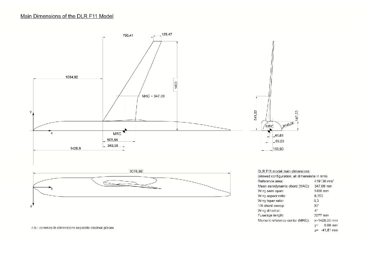
Geometric Reference Parameters:
- Reference area of the semi-span model = Sref/2 = 419130 mm2
- Mean aerodynamic chord (MAC) = 347.09 mm
- Wing semi-span = 1400 mm
- Moment reference center (MRC): x=1428.90 mm, y=0.0 mm, z=-41.61 mm
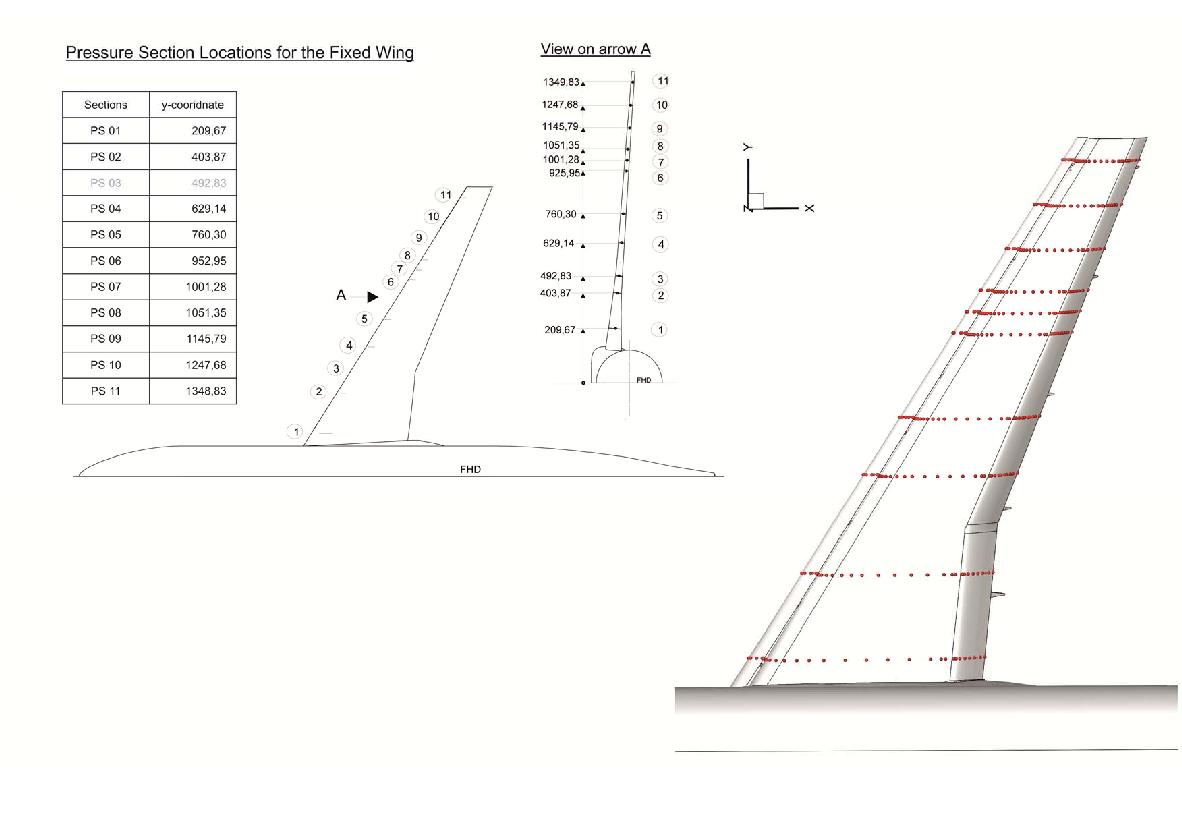
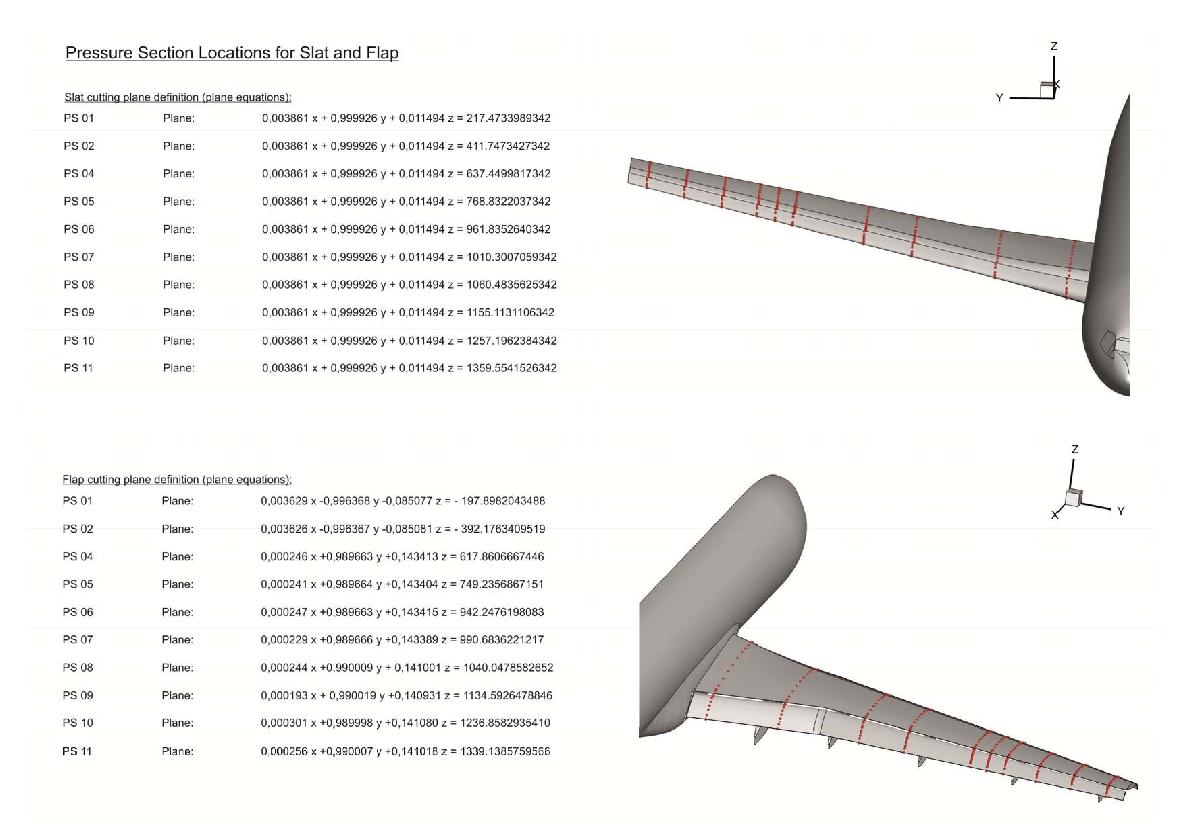
The following descriptive diagrams give additional details concerning the configuration geometry and
reference parameters. Also included are definitions of the planes containing the
pressure taps on the slat and flap when rotated into landing configuration
(slat 26.5 deg, flap 32 deg):
Note that Tecplot macro files and instructions for extracting cuts along the appropriate pressure section locations are provided on
the Data Submittal Forms & Postprocessing Info page.
Return to: High Lift Prediction Workshop Home Page
Privacy Act Statement
Accessibility Statement
Responsible NASA Official:
Li Wang
Page Curator:
Li Wang
Last Updated: 03/28/2014


