SUGGESTED WORK FOR 2012 AIAA SPECIAL SESSIONS
1st
AIAA CFD High Lift Prediction Workshop
General Information
Researchers interested in participating in the HiLiftPW special sessions at the AIAA meeting in June 2012
(New Orleans) are asked to submit an abstract by the deadline (see
home page).
First, review previous Trap Wing results from HiLiftPW-1 in order to familiarize yourself with
the strengths and weaknesses of state-of-the-art prediction methods for this configuration:
(Data files of HiLiftPW-1 participant results can be downloaded from the
HiLiftPW-1 Results page, if desired.)
Then, submit an abstract describing your proposed research on the Trap Wing configuration.
Suggested additional research studies can include, but are not limited to:
Many of the above-mentioned investigations have been done to some degree in previous research.
Abstracts that explore new ground or make new insights will have a greater likelihood of acceptance.
Accepted authors are expected to write a full-length AIAA paper and make a presentation at the
30th AIAA Applied Aerodynamics Conference, June 25-28, 2012 in New Orleans, LA.
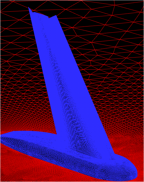
Researchers may either make use of existing Trap Wing grids (see
HiLiftPW-1 Grids Page),
or create their own.
Data submission is strongly encouraged, but not mandatory. Please fill out and
submit the following Tecplot-readable Data
Submittal Forms:
One set of forms (1 plus 2 plus 3) covers one complete set of runs. If a participant
runs more than one set of grids, more than one CFD code or methodology, or more than one
turbulence model, then one set of forms would be submitted for each grouping.
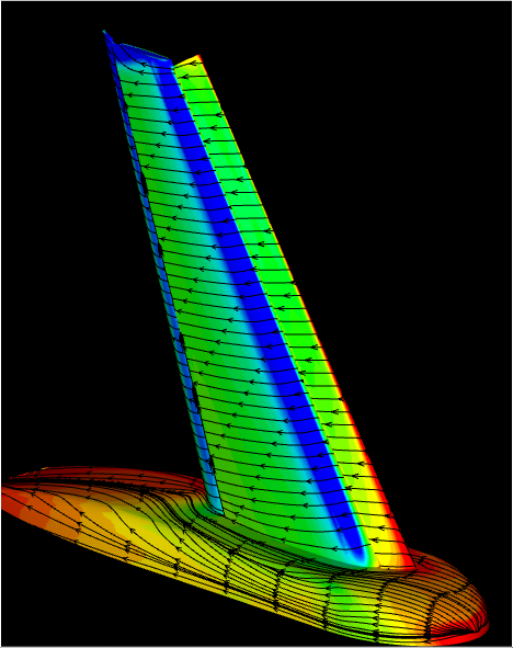
Note that Data Form 2 requires that data be extracted along 7 specific cuts on the configuration.
These correspond to locations for which experimental pressure tap data are available. See the text file:
ss-extraction.planes.deployed-config1.txt
Note that these 7 cuts represent considerably less data than was required previously for HiLiftPW1.
(If you are interested, details about the additional cuts used previously for HiLiftPW1 can be found on the
HiLiftPW1 Submittal Page).
Tecplot macro files for extracting surface CP data are given here:
ss-extractplanes-config1.mcr
ss-renamezones-config1.mcr
The macro files can be used as follows.
- Load (into Tecplot) a data file
containing the solid walls along with your CFD solution on the walls.
Be sure that X, Y, and Z are in full scale inches.
- These macros are for the half-plane geometry defined in the -Y direction;
therefore if your geometry lies only in the +Y sector, you must first flip or mirror
your data (e.g., using Data-CreateZone-Mirror-XZPlane).
- If CP is not one of your solution variables, then use
Tecplot to create it.
- Then, run the macro (ss-extractplanes-config1.mcr)
The macro will create 7
new zones of extracted data at all the cuts asked for.
- Under Data-Delete-Zone, delete all original zones so that only the 7 newly
created zones are left.
- Run the renaming macro (ss-renamezones-config1.mcr)
to rename the new zones appropriately.
- These cuts can then be written out by the user to an ASCII file (use point format);
write out the variables X, Y, Z, CP.
- The zones from this file should then be relatively easy
to include into the Data Form 2. If you can limit the extractions to occur
only on the appropriate elements, then do so. But if the extraction process
also extracts unneeded areas (e.g., if the extraction along slat50
also includes data on the main and flap), then do not worry... these areas
will be ignored.
For Data Form 3, use the experimental velocity probe data files to extract CFD velocities at the same locations.
In Tecplot, this can be done as follows:
- Load your volume solution into Tecplot.
- Your X, Y, and Z variables should be in model coordinates, inches, and should be
labeled as X, Y, and Z. If not, use Tecplot to rename them.
- If uoverVinf, voverVinf, woverVinf, and VeloverVinf are not among
your solution variables, then use Tecplot to create them.
- Load (add) the X, Y, Z locations from each of the experimental data files
(e.g., from VelAlpha28Eta83AftFlapRun059.dat). These data are located on the page:
Experimental Data: Velocity Probes).
- Use Data - Interpolate - Linear to interpolate your solution onto the
experimental data points.
- Write these interpolated data to an ASCII file (use point format);
write out the variables X, Y, Z, uoverVinf, voverVinf, woverVinf, VeloverVinf.
Submit all data files by email to: hiliftpw@gmail.com
by June 12, 2012.
Return to: High Lift Prediction Workshop Home Page
Page Curator and NASA Official Responsible for Content
Li Wang
Last Updated
February 15, 2012
Privacy Act Statement
Accessibility Statement

